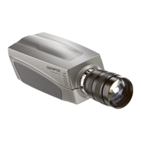
Specifications
101
i--SPEED LT, i--SPEED 2
Feature connector 26 way high density D sub female
Pinout 1 +12V 2 Power ground
3 Trigger input 4 Trig in ground
5 Trigger output 6 Trig out ground
7 Sync input 8 Sync in ground
9 Sync output 10 No connect
11 Analogue signal
input 1
12 Analogue in ground
1
13 Analogue signal
input 2
14 Analogue in ground
2
15 No connect 16 RS--232 ground
17 RS--232 Tx (data out
of iSPEED, not used)
18 Sync out
19 RS--232 Rx. (data in
to iSPEED, not used)
20 RS--232 ground
21 No connect 22 S--Video Y
23 S--Video Y ground 24 S--Video C
25 S--Video C ground 26 No connect
Sync in Level: 5V TTL, 12V maximum
Impedance: 10k ohms to ground ±10%
Sync out Level: 5V nominal TTL
Impedance: 50 ohms ±10%
Trigger in Level: 5V TTL, 12V maximum
Impedance: 10k ohms (pulled to +5V for trigger switch)
Trigger out Level: 5V nominal TTL
Impedance: 50 ohms ±10%
Analogue signal
input 1 and 2
Level: 0 to 5V analogue
Impedance: 10k ohms to ground ±10%
Bandwidth: 100KHz minimum
S--Video Industry standard signals, NTSC / PAL as for BNC
Power output 12V @ 10W max
Note: Further data on Analogue input, sync and trigger can be found in System
Performance

 Loading...