SUCTION PUMP KV--5
4
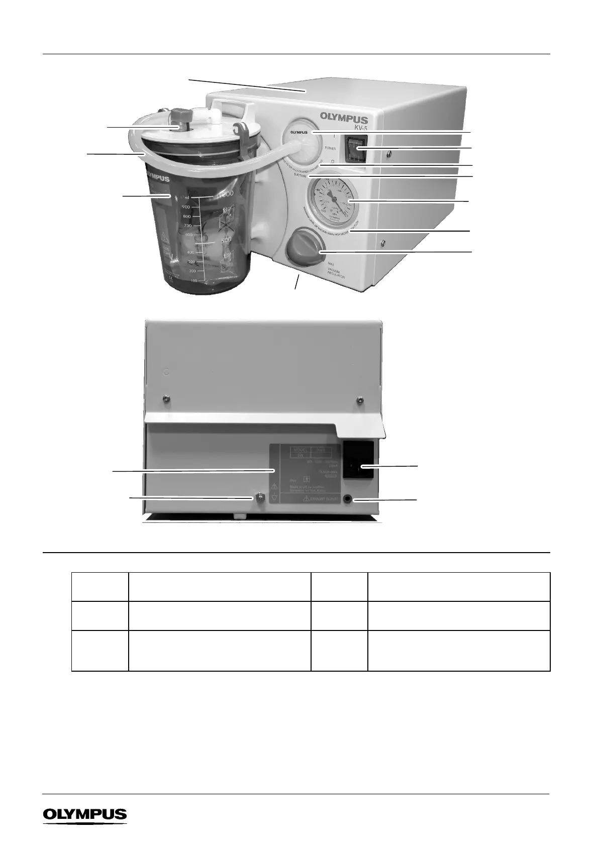
1.4 Features
FIGURE 1-1
Suction jar and lid
Power switch
Microbial filter
Label 1
Label 3
Rear panel
Filter
connecting tube
Label 2
IEC power receptacle
(with integral fuses)
Potential
equalisation
terminal
Label 4
Vacuum gauge
(for indication only)
Vacuum
regulator
Exhaust outlet
Single--use
suction liner
Label 6
Label 5
1.5 Labels
Label 1 CHANGE FILTER DAILY OR WHEN
CONTAMINATED
Label 2 SUCTION
Label 3 MAXIMUM LEVEL OF VACUUM 85kPa
HIGH VACUUM / HIGH FLOW
Label 4 RATING PLATE
Label 5 CAUTION: REMOVE TRANSIT SCREWS
FROM BASE BEFORE USE. REPLACE
BEFORE TRANSPORTATION.
Label 6 CAUTION: REMOVE TRANSIT SCREWS
BEFORE USE. REPLACE BEFORE
TRANSPORTATION.
NOTE
Label 5 should be removed and stored safely when the transit screws have been removed (Section 2.1). When
the unit is to be transported, replace the transit scr ews and affix the label on top of the unit.
Label 6 is permanent.