11
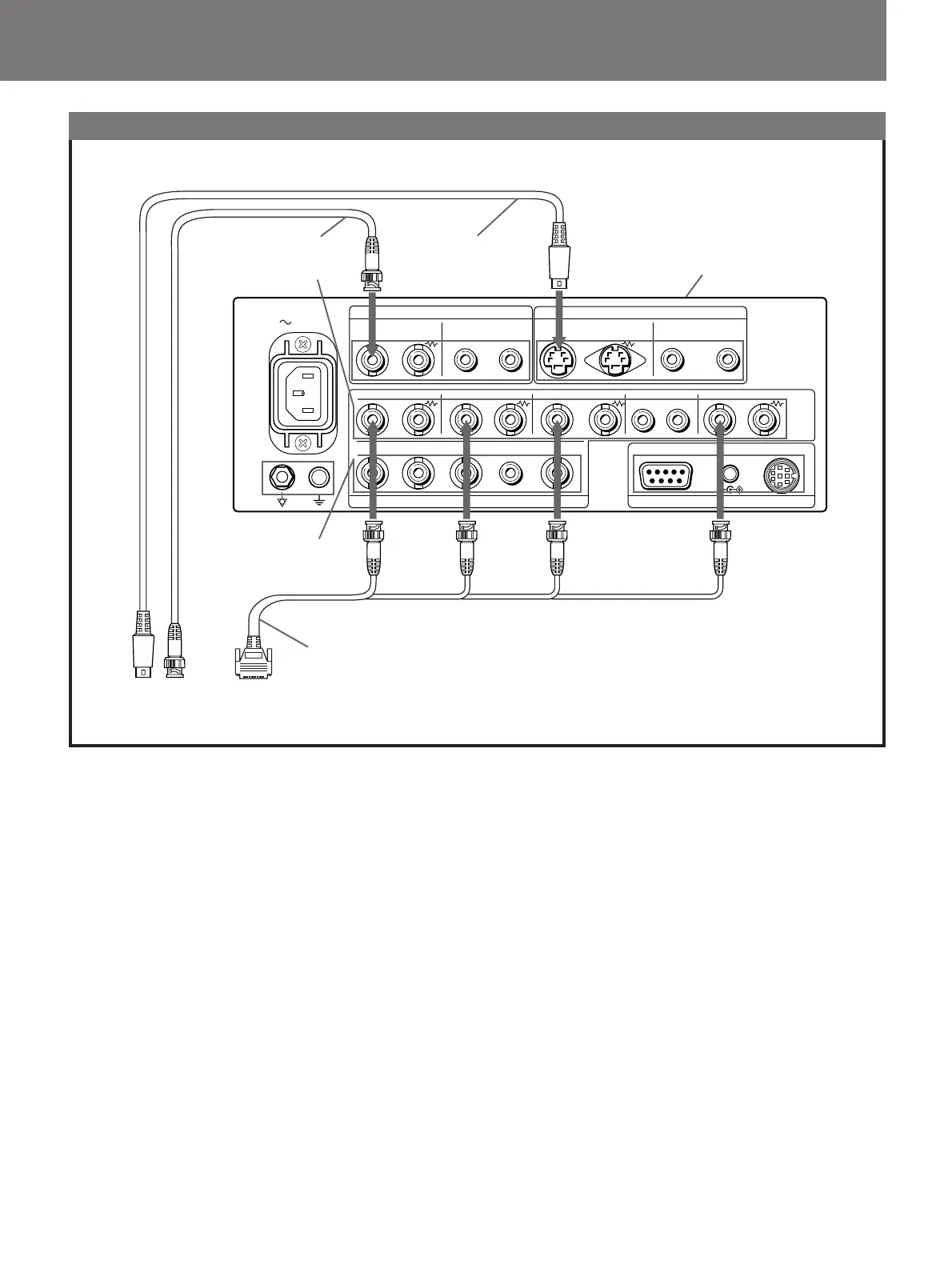
Connection to OES Video System
1 Connect any cable of the monitor cable, Y/C cable, or
BNC cable to the video output connector of the Camera
Control Unit.
2 Connect cables to this unit as shown in the figure.
LINE A
LINE B
IN OUT
OUT
IN OUTOUT
VIDEO AUDIO
AUDIO
AUDIO
AC IN
R/R–Y G/Y B/B–Y
EXT SYNC
G/Y
AUDIO
REMOTE 1RS-232C
Y/C
IN
R/R–Y
B
A
IN OUT IN OUT IN OUT IN OUT IN OUT
DC OUT
REMOTE
EXT SYNC
RGB/COMPONENT
B/B–Y
INININ IN IN
8V/0.8A
IN
RGB/COMPONENT B
connectors
RGB/COMPONENT A
connectors
BNC cable
Y/C cable
S
RG
B
Monitor INPUT/OUTPUT connectors
Y/C
N
Monitor cable