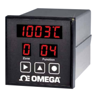
Setup - Power the CN 616 controller
1. MODEL SELECTION.
To comply with the requirements, the following model must be
selected:
Standard control, Hi / Lo Alarm with Non Latching Relay, ºF.
Type “K” thermocouple
Looking on page 28 in the Manual the model will be coded as: 2 3 0 4.
2 - Hi / Lo Alarm
3 - Non latching relay, *F
0 - Standard control
4 - Type “K” thermocouple
Using procedure outlined on the inside back cover of this reference
card, load the above model number into the controller.
NOTE -
If Function 99 appears during setup- it means that the password
protection is enabled. Follow instructions on page 25 of the Manual to
enter the password. Password is factory preset at 1 0 1 1. It may be a
good idea to disable the Password protection at this time. Use proce-
dure on page 27 and load “0” in Function 32. If password protection is
desired, enable the password after the Controller setup is completed.
2. ZONE DISABLE - Page 27
Since only 4 zones are used, zones 5 & 6 should be disabled. Using
setup procedure outlined above set 31 within the Function 71 and
follow the zone enable procedure in the Manual on page 27.
3. ZONE DISPLAY TIME - Page 29
Using the setup procedure outlined above set 35 within Function 71
and follow the Zone display time instructions in the Manual on page 29.
4. SET SETPOINT - Page 29
Using setup procedure outlined on the inside back cover of this refer-
ence card, select Function 72 instead of 71. Select sub function 36
(Setpoint) and follow the procedure
43
On page 29 of the Manual to load the following setpoints :
Z1 - 400 º F
Z2 - 500 º F
Z3 - 530 º F
Z4 - 300 º F
Skip zones 5 & 6.
5. HIGH ALARMS - Page 30
Select Function 72 as above, select sub function 37 (Hi - Alarm).
Follow the procedure Outlined on page 30 in the Manual and set the
following alarms :
Z1 - 15 º F
Z2 - 15 º F
Z3 - 15 º F
Z4 - 20 º F
6. LOW ALARMS - Page 30
Select Function 72 as above, select sub function 38 ( Lo Alarm).
Follow the procedure Since only 4 zones are used, zones 5 & 6
should be disabled. Using setup procedure
Z1 - 20 º F
Z2 - 15 º F
Z3 - 20 º F
Z4 - 20 º F
7. PID CONTROL - Pages 31, 32, 33.
Even with the AUTOTUNE system certain parameters must be set
manually, these are :
CYCLE TIME - Minimum recommended 4 seconds
HYSTERESIS - Typical 1 º F
PID ZONES - Z1, Z2, Z3, Z4.
COOLING ZONES - None
Using the procedures outlined on pages 31, 32 & 33 of the manual,
load the above numbers.
44
 Loading...