4
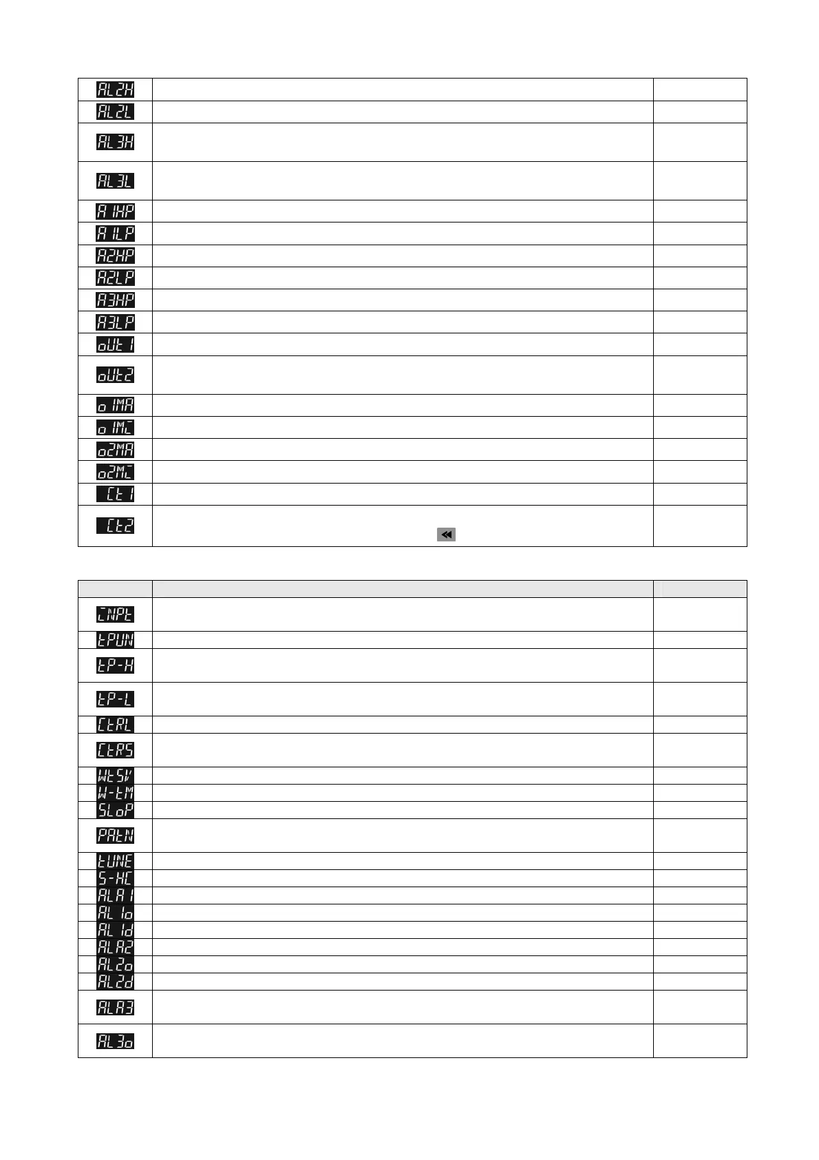
ALARM2 HI
GH:
Upper limit alarm
2 (displa
y according to the setting in ALARM mode)
4.0
ALARM2 LOW: L
o
wer limit alarm 2 (displa
y
according to the setting in ALARM mode)
4.0
ALARM3 HIGH:
Upper limit alarm 3 (set OUT2 to ALARM mode and it will display according to the
setting in ALARM mode)
4.0
ALARM3 LOW: Low
er limit alarm 3 (set OUT2 to ALARM mode and it will display according to the
setting in ALARM mode)
4.0
ALARM1 HIGH
PEAK: High peak value 1
ALARM1 LOW P
EAK: Low peak value 1
ALARM2 HI
G
H
PEAK: High peak value 2
ALARM2 LOW PEAK: Low peak value 2
ALARM3 HI
GH
PEAK: High pea
k value 3 (displa
y when OUT2 is set to alarm mode)
ALARM3 LOW PEAK: Low peak value 3 (display
when OUT2 is set to alarm mode)
OUT
1
: Displa
y
and adjust output value of 1
st
output group
0.0
OUT2: Display
and adjust output value of 2
nd
output group (display when OUT2 is set to
Heating/Cooling Mode)
0.0
O
U
T1 MAX: Upper
limit %
of 1
st
output group (perform linear calculation again)
100.0
OUT
1 MIN.: Lo
w
er limit % of 1
st
output group
0.0
O
U
T2 MAX: Upper
limit %
of 2
nd
output group (display when OUT2 is set to Heating/Cooling Mode)
100.0
O
U
T2 MIN: Lower
limit %
of 2
nd
output group (display when OUT2 is set to Heating/Cooling Mode)
0.0
CT1: Displa
y
C
T
1 current (display when external CT is connected to CT1)
CT2: Display CT
2 current (display when external CT is connected to CT2)
press
to return to target temperature setting.
【Initial Setting Mode】Para
met
er Settings:
Display Description Factory Setting
INPUT: Set input type (
refer to “Temperature Sensor Type & Temperature Range Chart” for the
selection of Thermocouple or Platinum Resistance types.)
PT
TEMP. UNIT: Set temperatur
e unit /℃ ℉(it wil not be displayed when in analog input mode) ℃
TEMP. HIGH: Set up upper temper
ature limit (the upper limit setting is different for different types of
sensor)
850.0
TEMP. LOW: Set up lower temperature limit (the lo
wer limit setting is different for different types of
sensor)
-200.0
CONTRO
L: Select control modes ( 5 different modes: ON-OFF, PID, MANUAL, FUZZY and 2PID) PID
CONTRO
L SV provides 4 different options: CONS; PROG; SLOP; and REMO. REMO mode is
available when REMOTE function is added.
CONS
WAIT SV: Set up waiting temperat
ure (display when in programmable control)
WAIT TIME: Set up wa
iting time(display when in programmable control)
SLOP: Set up start slope (display
when in programmable control)
PATTERN: Select pattern to be edited (display
when in programmable control, there are 16 patterns
and each pattern includes 16 steps. Setting parameters are OFF, SAVE, 0~F.)
OFF
TUNE: Select AT or ST (display when in PID/2PID
control mode) AT
SELECT HEAT/COOL: Select heating, cooling or dual output heati
ng and cooling H1H2
ALARM1 SET: Set up Alarm 1 mode (refer to
“Alarm Output” for more setting on modes) 0
ALARM1 OPTION:
Set up Alarm 1 options (refer to “Alarm Output” for more setting on modes) 0
ALARM1 DELAY: Set up Alarm 1 delay
(refer to “Alarm Output” for more setting on modes) 0
ALARM2 SET: Set up Alarm 2 mode (refer to "Ala
rm Outputs") 0
ALARM2 OPTION: Set up Alarm 2 options (refer t
o “Alarm Outputs” ) 0
ALARM2 DELAY: Set up Alarm 2 delay
(refer to “Alarm Outputs” ) 0
ALARM3 SET: Set up Alarm 3 mode (refe
r to "Alarm Output")(display when OUT2 is set to ALARM
mode)
0
ALARM3 OPTION: Set up Alarm 3 options (refer t
o "Alarm Output") (display when OUT2 is set to
ALARM mode)
0

 Loading...