00070193.DOC, Version 1.0
16/20
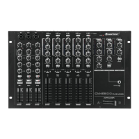
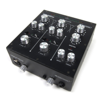
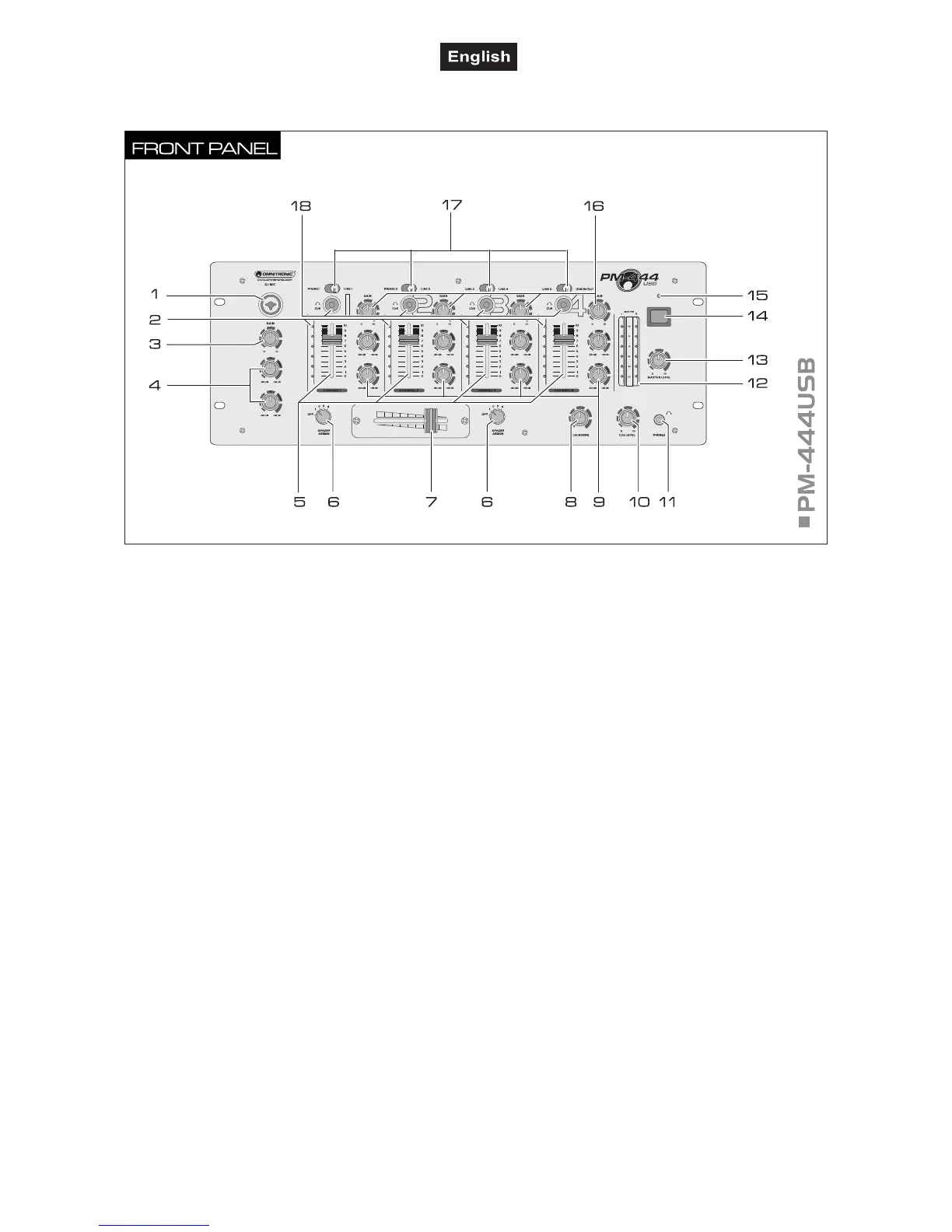
4.2 Operating elements and connections
DJ microphone input
Input for connecting a DJ microphone via an
XLR plug or 6.3 mm plug.
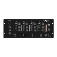
2 Level LED meter
LED meter for channels 1 to 4; the level is
indicated ahead of the corresponding channel
fader (prefader).
3 Gain control
Level control for the DJ microphone.
4 Tone controls HIGH, LOW
2-way equalizer for the DJ microphone: HIGH
and LOW.
6 Channel faders
Level controls for channels 1 to 4.
7 Assignment switches X-FADER ASSIGN
Select the channel for crossfading with the
crossfader. If crossfading is not required, set
both switches to "OFF".
8 Crossfader
For crossfading between two of the channels 1
to 4 selected with the assignment switches. In
mid-position, both channels can be heard at the
same volume.
Control CUE MIXING
For selecting and crossfading the monitoring
signal for the headphones output:
• left position: the prefader level of the input
channel of which the button CUE is pressed is
monitored.
• right position: the music program currently
playing is monitored ahead of the master
control.
10 Tone controls HIGH, LOW
2-way equalizer for channels 1 to 4: HIGH,
LOW.
11 Level control CUE LEVEL
Level control for headphones output.
12 Headphones output
6.3 mm jack for connecting stereo headphones
(impedance T16 ).
13 Output level LED meter
6-digit LED meter of the master signal within the
range of -13 dB to +3 dB.
14 Master control
Level control for the master signal at the master
outputs.
15 Power on/off
Press this button to turn the unit on and off.
 Loading...