Chapter 2 - What is a DL50?
Manual Rev. 1.01 Page 9
The Ethernet status is shown as three LEDs. The Link LED lights whenever an Ethernet 10BaseT
network link connection is found. The yellow TX LED lights briefly whenever an Ethernet frame
is being transmitted. The Active LED lights whenever a network connection, such as ftp, Telnet,
or a pass-through connection, is active. These LEDs can be used to see that a network cable
connection is made and when the DL50 transmits over the network.
I/O 1 has two LEDs associated with it. The left LED is a received data (RX) LED. The right LED
is a transmitted data (TX) LED. The TX LED is normally on and green when the unit is powered
up. The RX LED is off when no cable is connected to the serial port and green when a cable is
connected and no data transfer is taking place. When an RS-232 line is connected and idle, both
the TX and RX LEDs will be lit green. When data is transmitted, the TX LED quickly alternates
green and red. These LEDs can be used to verify that a cable is connected (the LED is lit) and that
data is being transmitted or received (the LEDs flicker between red and green). I/O 2 has a CTS2
LED in addition to pair of TX and RX LEDs. CTS2 lights when a clear to send signal is received
on I/O2.
The DL50 has five LEDs to indicate file full status. A solid lit LED indicates the database
percentage is at or over the value for that LED. A blinking percentage full LED indicates the
database has less than the amount indicated by that LED, but more than the previous.
The Power LED has two operational states. Normally the power LED is lit steadily, with a short
blink once every ten seconds. This ‘heartbeat’ signal indicates typical operation. The second state
occurs during the boot sequence, where it will blink once every second until the boot sequence is
complete and two beeps are heard.
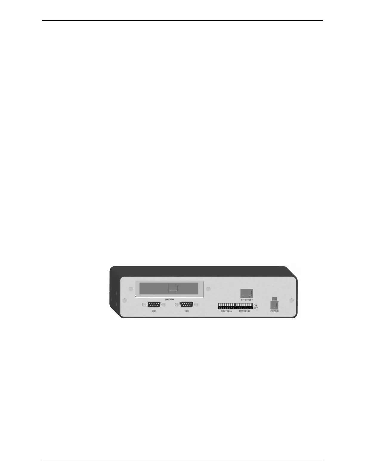
2.4 - Back Panel
Serial Ports
Figure 4: Complete DL50 Back Panel
Both DB9 serial ports are DTE and male. This configuration is similar to that used on the COM
ports of an IBM-compatible PC. The following figure shows the pin configurations of these ports: