EasyManuals Logo

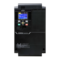
Omron 3G3RX2 Series Instruction Manual

Omron 3G3RX2 Series
88 pages
To Next Page IconTo Next Page
To Previous Page IconTo Previous Page
Page #70 background imageLoading...
Page #70 background image
Control circuit
26
Control circuit
Outline of control circuit
Control circuit
terminal area
Backup
24V power supply
terminal
P+
P-
1/RS
2/SCHG
3/JG
4/FRS
5/2CH
6/CF1
7/CF2
8/RV
9/FW
A/EXT
B/USP
COM
CM1
Interface
24V power supply terminal
P24
H
Ai1
Ai2
Ai3
L
(+)
(-)
10V)
(0V)
TH+
AL2
AL1
AL0
16A
16C
11/RUN
12/FA1
13/FA2
14/IRDY
15/OL
CM2
FM
CM1
Ao1
Ao2
L
SP
SN
SP
SN
RP
P24S
STC
CMS
ST1
ST2
ED+
ED-
TH-
L
L
10V
10V
20mA
10V
10V
20mA
20mA
Voltage input
Current input
Voltage input
Current input
Input terminal
Thermistor
STO input
STO confirmation output
Analog
input 3
Analog
input 2
Analog
input 1
P24
CM1
DC24V
P24
CM1
P24
IN
EX
Source
Sink
(SW5)
(SW6)
(SW1)
(SW2)
(SW3)
(SW4)
16/ZS
Operation section
USB
RJ45
P
C (P
roDriveNext)
LCD operator
20mA
You can switch between
the sink logic and
source logic for input
terminals by using SW6.
* The signal ground for RS485
terminal is CM1
RS485 terminal
Modbus
communication
Output terminals
* Supporting sink/source
Relay 1A contact
Alarm relay 1C contact

Other manuals for Omron 3G3RX2 Series

Questions and Answers:

Question and Answer IconNeed help?

Do you have a question about the Omron 3G3RX2 Series and is the answer not in the manual?

Omron 3G3RX2 Series Specifications

General IconGeneral
BrandOmron
Model3G3RX2 Series
CategoryInverter
LanguageEnglish

Related product manuals