Control circuit
32
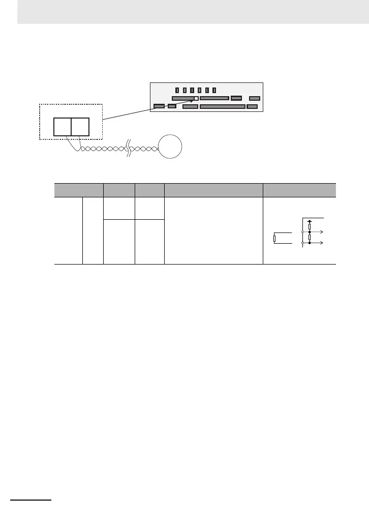
■External thermistor
(Wiring example)
Terminal
symbol
Terminal
name
Description Electrical characteristics
Thermistor
terminal
Analog
input
TH+
External
thermistor
input
Connect to an external thermistor to make
the inverter trip if an abnormal temperature
is detected.
Connect the thermistor to TH+ and TH-.
The impedance to detect temperature
errors can be adjusted within the range 0Ω
to 10,000Ω.
[Recommended thermistor properties]
Allowable rated power: 100 mW or more
Impedance at temperature error: 3kΩ
DC 0 to 5V
[Input circuit]
TH-
Common
for external
thermistor
TH-TH+
External thermistor
terminals
Thermistor
Control circuit terminal
• Twist the cables connected from a thermistor to the TH
terminal only between TH+ and TH-, and separate the
twisted cables from other cables.
• Since very low current flows through the cables
connected to the thermistor, separate the cables from
those (power line cables) connected to the main circuit.
• The length of the cables connected to the thermistor
must be 20 m or less.
DC5V
1kΩ
2kΩ
TH-
TH+
Thermistor

 Loading...


