Conductive Level Controller 61F-GP-N2 3
Connections
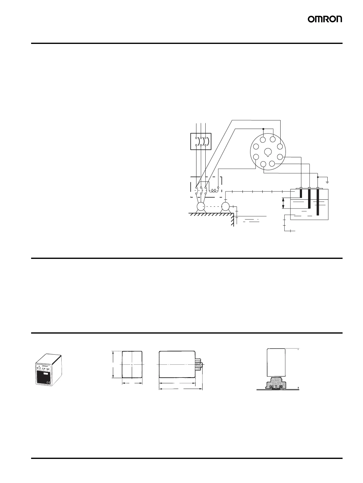
Automatic Water Supply and Drainage Control
1. Water supply
• Connect electromagnetic switch coil terminal A to Tb.
• The pump stops when the water level reaches E1 and starts when
the water level drops below E2.
2. Drainage
• Connect the electromagnetic switch coil terminal A to Ta.
• The pump starts when the water level reaches E1 and stops when
the water level drops below E2.
Note: 1. The diagram shows the connections for water supply. When
draining, change the connection Tb to Ta.
2. The earth terminal must be grounded.
Operation
The conductive type level controller consists of a plug-in controller
connected to a set of stainless steel probes. These are cut to length
and inserted vertically into the liquid. A low voltage is applied
between these probes and the earth probe (or tank, if it is electrically
conductive). The water provides a current between the earth probe
and the high-level probe. The output relay in the controller is ener-
gized when the water level reaches the high-level probe and de-ener-
gized when the water level falls below it.
For two-point control a low-level probe is used as well. In this case
the relay does not de-energize until the water level falls below the
low-level probe. Using the low-level probe allows a wide differential
between switching a pump on and off, and can avoid excessive pump
operation during tank emptying or filling. If this differential is not
required, the low-level probe need not be connected.
Dimensions
Note: Note:All units are in millimeters unless otherwise indicated.
1
7
E1
E2
6
S1
S2
E3
8
2
3
5
Ta
Tb
Tc
Power source
220 or
240 VAC
MCCB
Electromagnetic
switch
Eart
Ta nk
Stop
Start
Reservoir
RST
4
A
M
P
E1
E2
E3
91
61F-
GP-N2
PF083A
70
84
38
49.4
38
80
70

 Loading...


