17
Appendix A. Instructions converted by Change Model on CX-Programmer
(1) The data type of operand is changed from BCD to binary for some instructions.
(2) The number of operands is changed for some instructions.
(3) Interrupt control instructions must be changed. (Use MSKS, MSKR, CLI, DI, and EI).
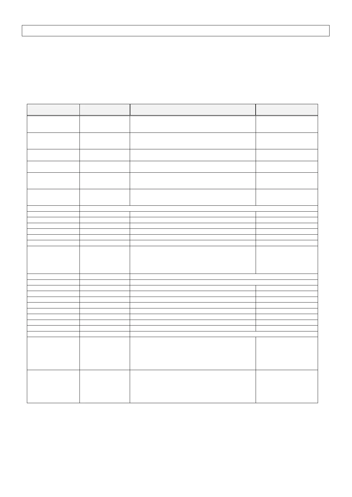
Refer to the list below for details. The table lists the instructions which differ between before and after conversion. The other
instructions remain unchanged after conversion.
Instruction for
C200HX/HG/HE
JMP0(515)
When #0 is set to the operand, JMP is converted to
JMP0 and the operand is deleted.
If a value other than #0 is set, the operand is the same.
<> #0: Same
JME0(516)
When #0 is set to the operand, JME is converted to
JME0 and the operand is deleted.
If a value other than #0 is set, the operand is the same.
<> #0: Same
#0 is added to the second operand.
FAL N → FAL N #0
#0 is added to the second operand.
FALS N → FALS N #0
The Work Area (WR) or Index Register (indirect) can be
used to specify the operand.
The Work Area (WR) or Index Register (indirect) can be
used to specify the operand.
Set a minimum cycle time in the PLC Setup.
#0 is added to the first operand.
MSG FM → MSG #0 M
The number of characters (words) to be registered from
the first message word is changed from 16 characters (8
words) to 32 characters (16 words).
To execute the keyboard mapping function, use the function on the touch panel.
The data type of the second operand is changed from
BCD to binary.
When a constant is specified, "#" is automatically
converted to "&".
When a word address is specified, change the data type
of the word from BCD to binary.
The data type of the third operand is changed from BCD
to binary.
When a constant is specified, "#" is automatically
converted to "&".
When a word address is specified, change the data type
of the word from BCD to binary.
 Loading...


