Appendix BSpecifications
161
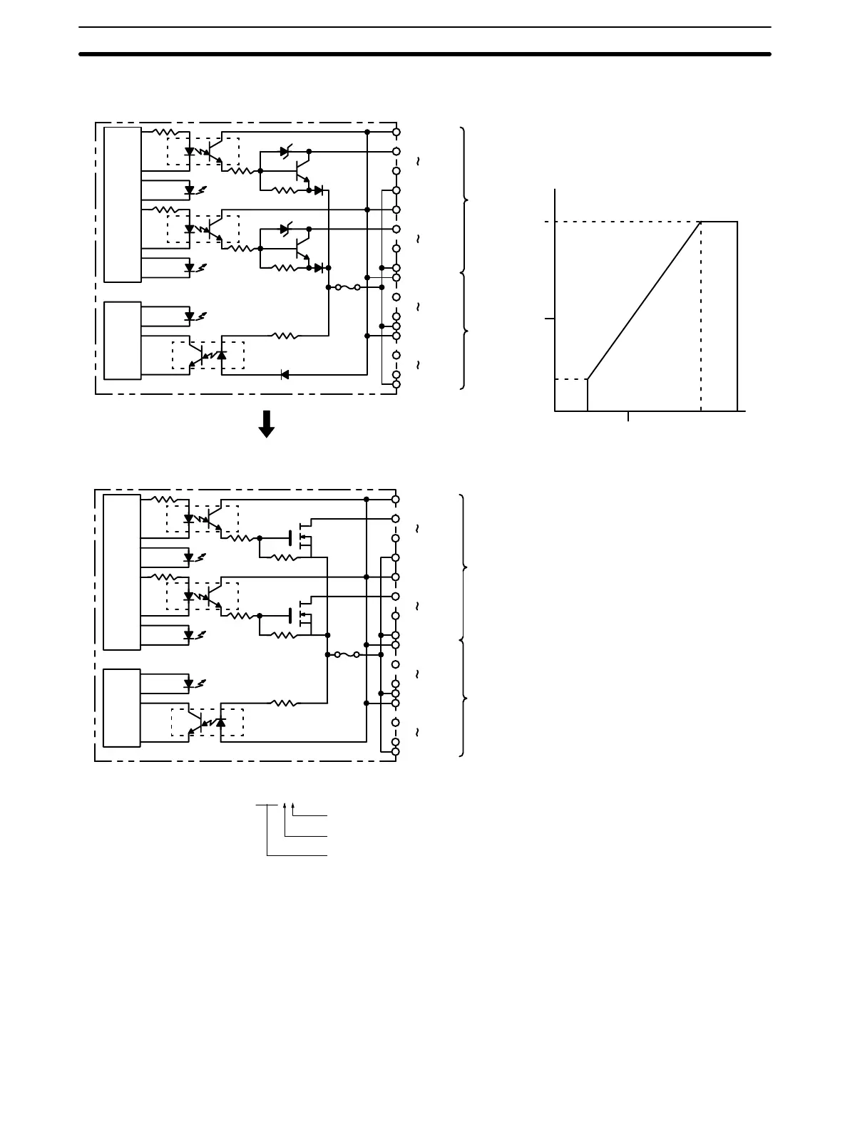
Circuit Configuration and Maximum Switching Capacity
Units manufactured on or before January 28th, 2000
(manufacturing numbers 2810 or earlier*)
Units manufactured on or after January 31st, 2000
(manufacturing numbers 3110 or later*)
Output
indicator
Fuse
(3.5 A)
F indicator
Output
indicator
OUT00
OUT07
COM
A
Internal
Circuit
4.5 to
26.4 VDC
4.5 to
26.4 VDC
OUT08
OUT15
COM
OUT00
OUT07
COM
B
OUT08
OUT15
COM
4.5 to
26.4 VDC
4.5 to
26.4 VDC
Output
indicator
Fuse
blowout
detec-
tion cir-
cuit
Fuse
(3.5 A)
F indicator
Output
indicator
OUT00
OUT07
COM
A
Internal
Circuit
4.5 to
26.4 VDC
4.5 to
26.4 VDC
OUT08
OUT15
COM
OUT00
OUT07
COM
B
OUT08
OUT15
COM
4.5 to 26.4
VDC
4.5 to
26.4 VDC
Fuse
blowout
detec-
tion cir-
cuit
Power Supply Voltage (V)
Max. Switching Capacity (mA/pt)
0 4.5 10 20.4 26.4
50
100
16
0
*Manufacturing Numbers
jjY9
Year: Last digit of calendar year; e.g., 1999→9, 2000→0
Month: 1 to 9 (January to September), X (October), Y (November), Z (December)
Day: 01 to 31
 Loading...


