Appendix BSpecifications
162
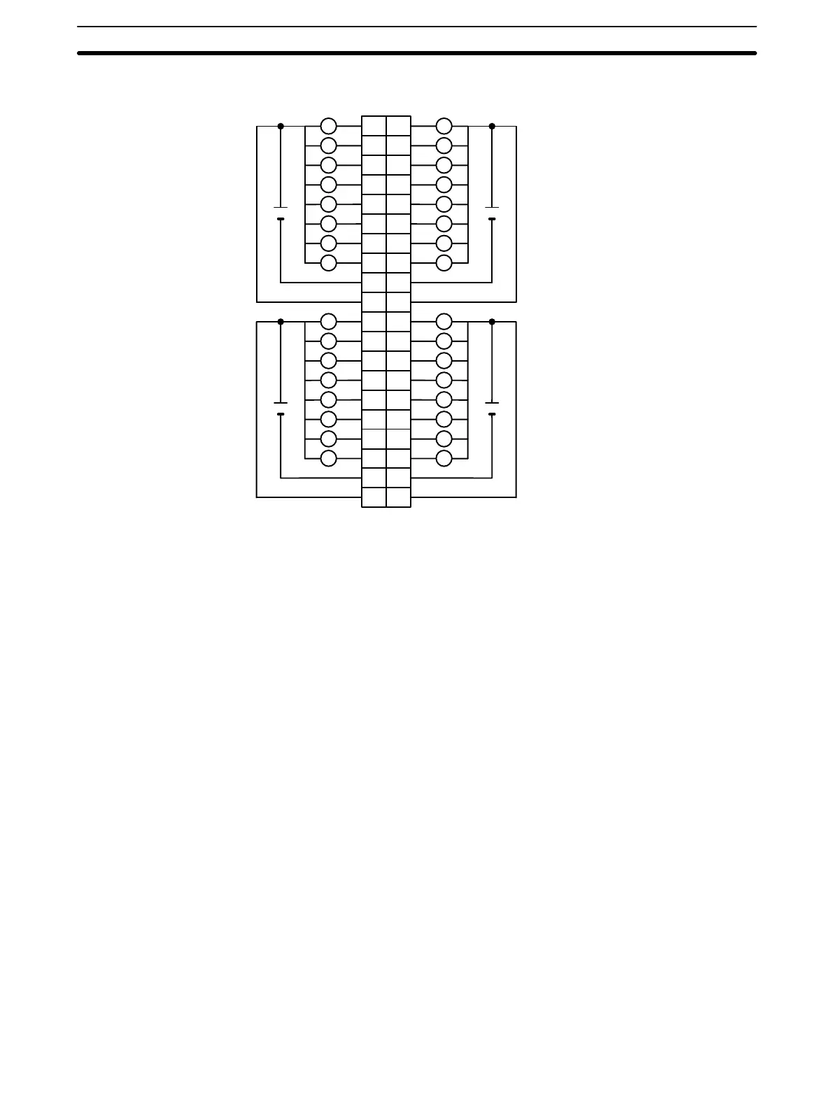
Terminal Connections
I/O word “m+1”I/O word “m”
L L
1
L
0
A
1
2
2
3
3
4
4
5
5
6
6
7
7
8
9
0
1
1
2
2
3
3
4
4
5
5
6
6
7
7
8
COM
9
B
L
L L
L L
L L
L L
L L
L L
L L
+
4.5 to
26.4 VDC
COM
+
10 10
11
12
13
14
15
16
18
11
12
13
14
15
16
17
18
19
20
19
20
17
8
9
10
11
12
13
14
15
COM
L
L
L
L
L
L
L
+
8
9
10
11
12
13
14
15
COM
L
L
L
L
L
L
L
+
Note 1. I/O word “m” is determined by the I/O number setting (m = IR 030 + 2 × I/O number).
2. When the fuse blows, the F indicator lights and the error flag in AR 02 corresponding to the I/O number is
turned ON. I/O numbers 0 to 9 correspond to AR 0205 to AR 0214. For the C200HX/C200HG/C200HX/
C200HW PC (0 to F Unit), the following AR and IR bits turn ON;
0 to 9 Unit: AR 0205 to AR 0214 and IR 28000 to IR 28009 turn ON.
A to F Unit: IR 28010 to IR 28015 turn ON.
3. The interruption of power from the external power supply is treated the same as a fuse blowout.
4. Connect power supply wiring to every COM terminal, even though the COM terminals are connected
internally.
5. When wiring output circuits, be sure to use the correct polarity for the external power supplies. Wiring
with incorrect polarity may result in erroneous operation of the load.
 Loading...


