Appendix BSpecifications
168
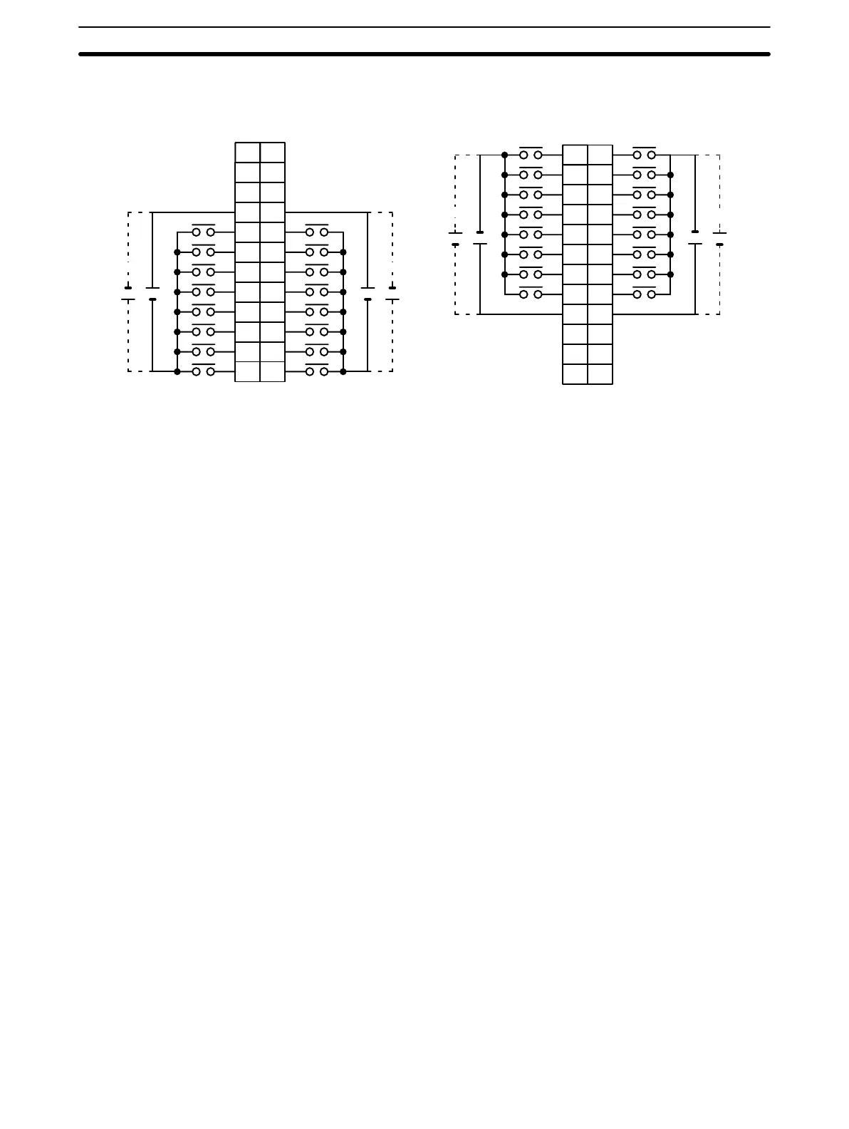
Terminal Connections
I/O word “n”
CN1
I/O word “n+1”
CN2
B
1
2
3
4
5
6
7
8
9
0
1
2
3
4
5
6
7
COM0
+
NC
10
NC
11
NC
NC
8
9
10
11
12
13
14
15
COM1
+
5 VDC
AB
0
1
1
2
2
3
3
4
4
5
5
6
6
7
7
8
COM2
9
8
9
10
11
12
13
14
15
COM3
+
+
NC
10
NC
11
NC
NC
NC
12
+
A
1
2
3
4
5
6
7
8
9
10
11
12
NC
+
5 VDC
NC
12
NC
+
5 VDC
+
5 VDC
1
2
3
4
5
6
7
8
9
10
11
12
Note 1. I/O word “n” is determined by the unit number setting (n = IR 100 + 10 × unit number). For the C200HX/
C200HG/C200HX/C200HW PC (0 to F Unit), the I/O word is as follows.
0 to 9 Unit: n= IR 100 + 10 × unit number
A to F Unit: n= IR 400 + 10 × (unit number – A)
2. When pin 2 of the Unit’s DIP switch is ON, input points 08 to 15 in connector 2 are high-speed inputs.
 Loading...


