ZEN V2 Units
13
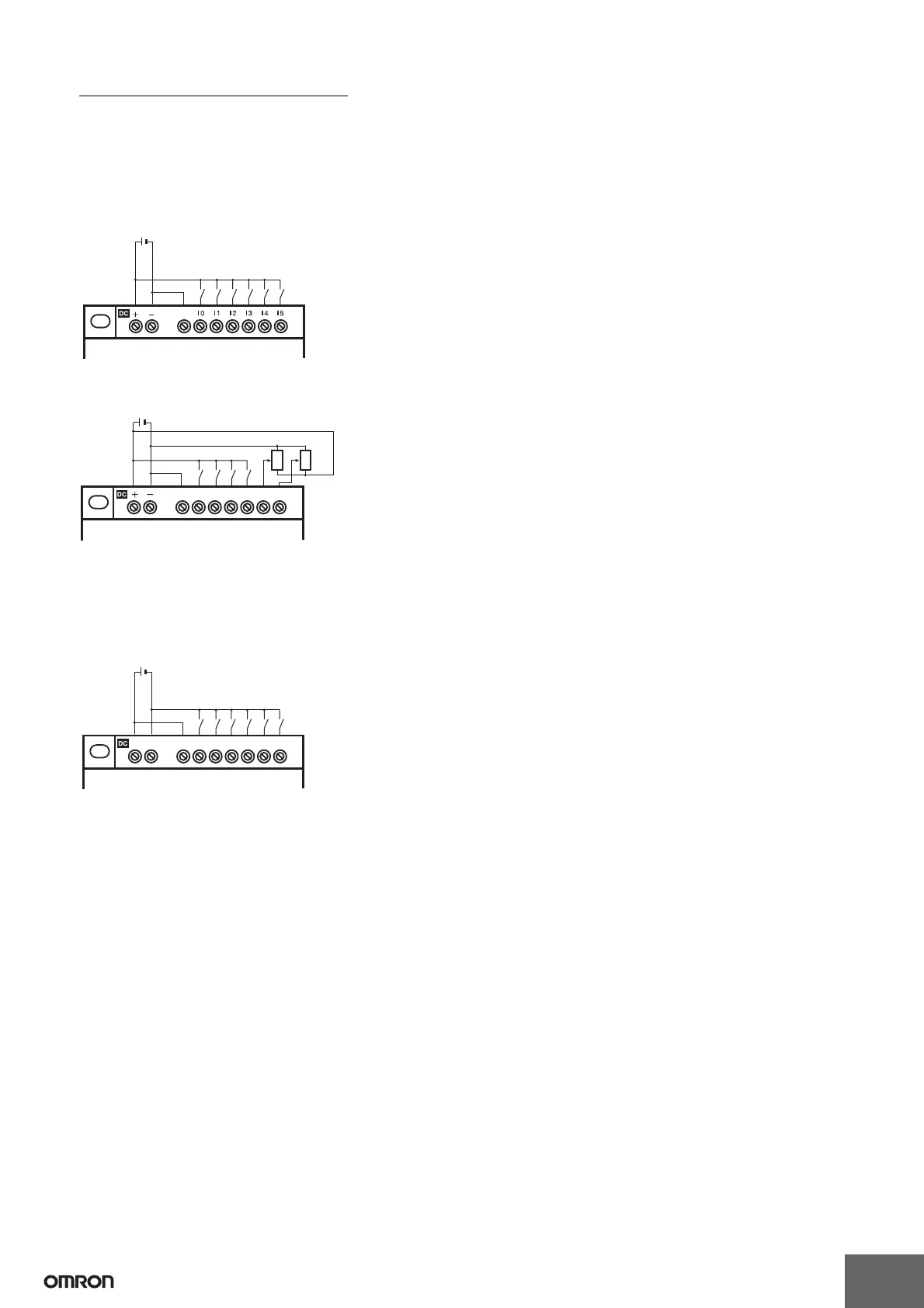
Units with DC Power Supply
Note: 1. Be sure to connect the COM terminal before turning ON the power supply. If the COM terminal is disconnected, or if the wiring is changed
after turning ON the power supply, a malfunction may occur.
2. Apply the power supply voltage through a relay or switch in such a way that the voltage reaches the rated value within 4 s. If the voltage
is applied gradually, the power may not be reset or unstable output operations may result.
CPU Units with 10 I/O Points
For Connections to Negative (−) Common (PNP Connection)
COM
CPU Unit with 10 I/O points
Input device
12 to 24 VDC
For Connecting Analog Input Devices to Input Terminals I4 and I5
CPU Unit with 10 I/O points
12 to 24 VDC
COM
I0 I1 I2 I3 I4 I5
For Connections to Positive (+) Common (NPN Connection)
COM
I0 I1 I2 I3 I4 I5
+ −
12 to 24 VDC
CPU Unit with 10 I/O points
Input
device
Note: When connected to the positive (+) common, I4 and I5 cannot be used as analog inputs.
Note: When connecting an analog input device, always connect the negative side to the COM terminal.