Appendix BSpecifications
110
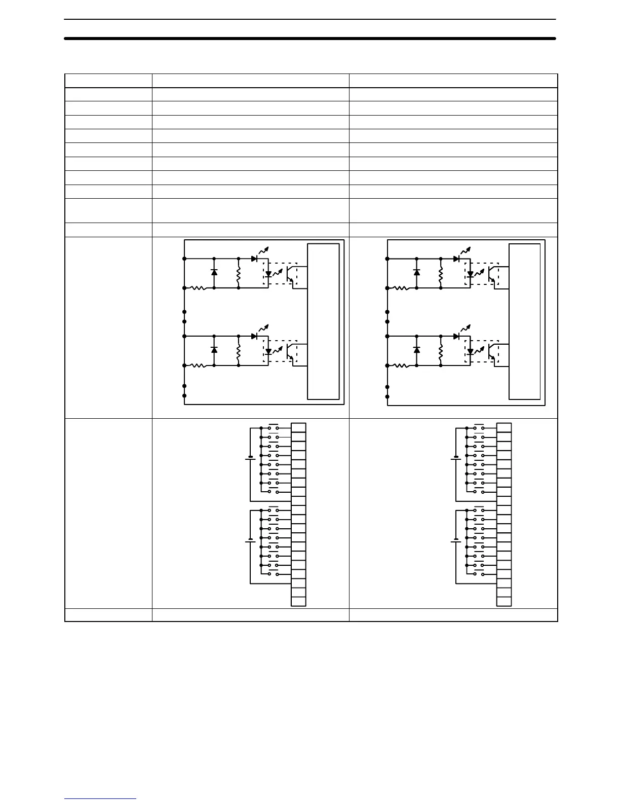
DC Input Units
Item 3G2A5-ID112 3G2A5-ID213
Input Voltage 5 to 12 VDC
+10%
/
–15%
12 to 24 VDC
+10%
/
–15%
Input Impedance
560
2.2 k
Input Current 16 mA typical (at 12 VDC) 10 mA typical (at 24 VDC)
ON Voltage 4.0 VDC min. 10.2 VDC min.
OFF Voltage 1.5 VDC max. 3.0 VDC max.
ON Delay 1.5 ms max. 1.5 ms max.
OFF Delay 1.5 ms max. 1.5 ms max.
No. of Inputs 16 (8 inputs/common, 2 circuits) 16 (8 inputs/common, 2 circuits)
Internal Current
Consumption
10 mA, 5 VDC max. 20 mA, 5 VDC max.
Weight 450 grams max. 450 grams max.
Circuit
Configuration
Inter-
nal
Circuit
COM
COM
IN 00
to
IN 06
IN 07
IN 08
to
IN 14
IN 15
6.8
k
6.8
k
560
560
Two-wire sensors cannot be connected.
Inter-
nal
Circuit
2.2 k
2.2 k
COM
COM
IN
00
to
IN 06
IN 07
IN 08
to
IN 14
IN 15
Inter-
nal
Circuit
1.8
k
1.8
k
Terminal
Connections
+
COM
NC
0
1
2
3
4
5
6
7
8
9
10
11
12
13
14
15
16
17
18
19
NC
0
1
2
3
4
5
6
7
8
9
10
11
12
13
14
15
COM
+
5 to 12 VDC
5 to 12 VDC
+
COM
NC
0
1
2
3
4
5
6
7
8
9
10
11
12
13
14
15
16
17
18
19
NC
0
1
2
3
4
5
6
7
8
9
10
11
12
13
14
15
COM
+
12 to 24 VDC
12 to 24 VDC
Dimensions A-shape A-shape

 Loading...


