Appendix BSpecifications
117
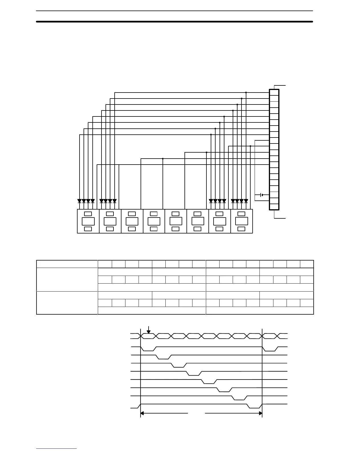
Connection Example 2 (Digital Switches)
This example shows how the ID212 DC Input Unit can be wired using digital switches. Just as the keys on the
keyboard
can turn ON
dif
ferent combinations of bits, the digital switches can control dif
ferent combinations of bits.
For example, the combination of inputs on switch no. 1 and input point 00 turn ON bit 00 of word n. (For the sake of
simplicity,
the figure below shows the digital switches wired to control 32 bits instead of 64 bits as was shown in
Example 1.) Wire STB 4, STB 5, STB 6, and STB 7 to access an additional 32 bits.
+
0
1
2
3
4
5
6
7
8
9
10
11
12
13
14
15
16
17
18
19
24 VDC
DATA
0
DAT
A 1
DAT
A 2
DAT
A 3
DAT
A 4
DAT
A 5
DAT
A 6
DAT
A 7
COM (+24)
STB 0
STB 1
STB 2
STB 3
STB 4
STB 5
STB 6
STB 7
COM (0 V)
+24 VDC
NC
-
+
-
+
-
+
-
+
-
+
-
+
-
+
-
+
87654321
D C B A COM
Switch
no.
87654321
The following table shows the combinations enabled by wiring digital switches as shown.
Terminal Number 15 14 13 12 11 10 09 08 07 06 05 04 03 02 01 00
Word n
Switch no. 4 Switch no. 3 Switch no. 2 Switch no. 1
0 1 0 0 0 0 1 1 0 0 1 1 0 0 0 1
STB 1 STB 0
Word n + 1 Switch no. 8 Switch no. 7 Switch no. 6 Switch no. 5
1 0 0 0 0 1 1 1 0 1 1 0 0 1 0 1
STB 3 STB 2
These pulses are input to bits 0 through 7 of word n.
32 ms
4 ms
Data 0 through
7
STB 0
STB 1
STB 2
STB 3
STB 4
STB 5
STB 6
STB 7
Timing

 Loading...


