Appendix BSpecifications
116
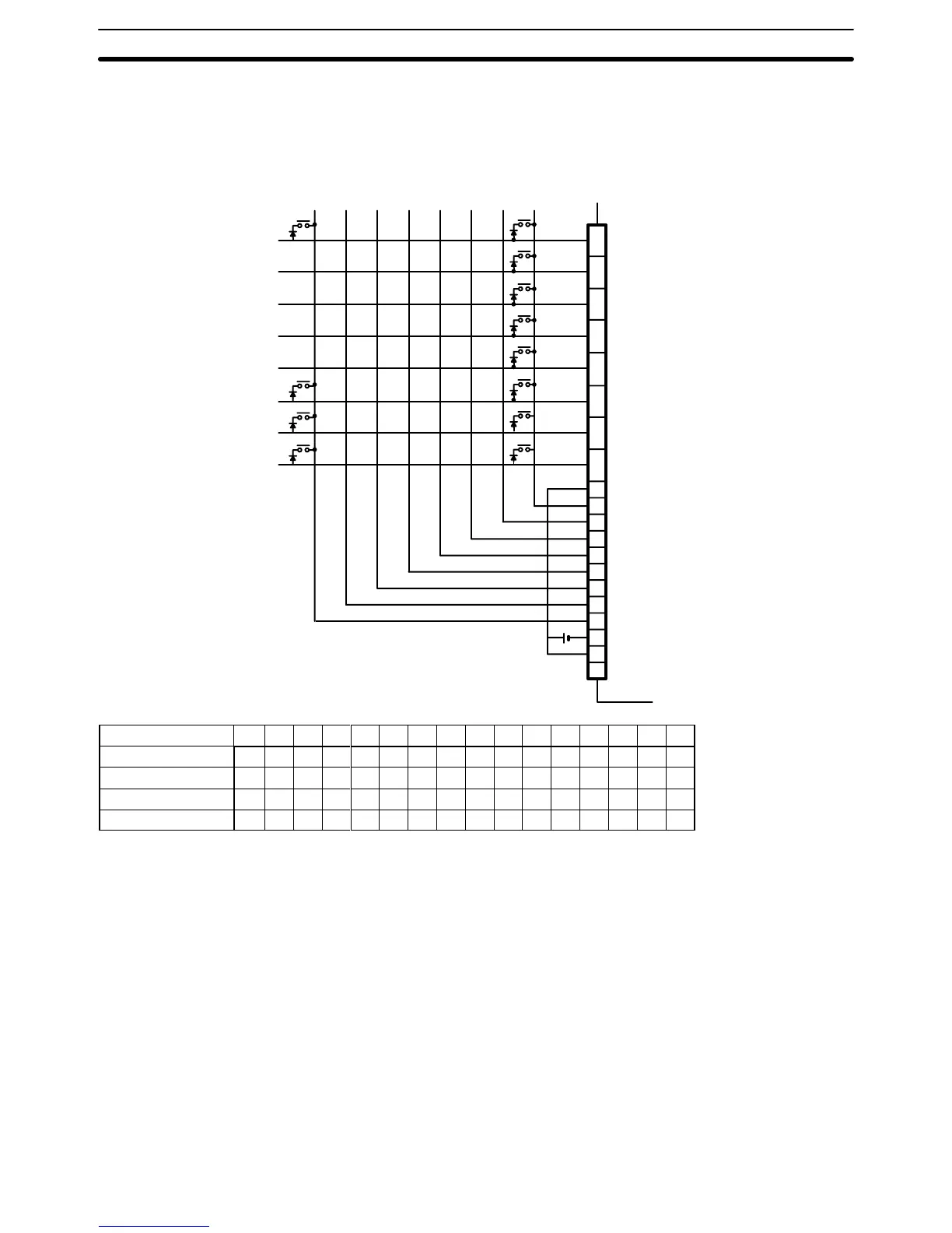
Connection Example 1 (Keyboard)
The
wiring diagram and table below show how the ID212 DC Input Unit can be wired using a specially wired key
-
board.
For example, if A on the keyboard is pressed, the combination of inputs on DA
T
A 0 and STB 9 turn
ON bit 00
of word n. Similarly
, the combination of inputs on DA
T
A 7 and STB 7 turn ON bit 15 of word n+3. The value of word n
depends on where the Unit is mounted.
+
0
1
2
3
4
5
6
7
8
9
10
11
12
13
14
15
16
17
18
19
24 VDC
A
B
C
D
E
DATA 0
DATA 1
DATA 2
DATA 3
DATA 4
DATA 5
DATA 6
DATA 7
COM (24 V)
STB 0
STB 1
STB 2
STB 3
STB 4
STB 5
STB 6
STB 7
COM (0 V)
24 VDC
NC
X
Y
Z
Terminal Number 15 14 13 12 11 10 09 08 07 06 05 04 03 02 01 00
Word n
E D C B A
Word n + 1
Word n + 2
Word n + 3 Z Y X
Note Because
the DC Input Unit is operated on an extremely small current, make sure there is adequate distance
between
the DC Input Unit wires and high-tension equipment or power lines. If this cannot be avoided, use
shielded cables when wiring the DC Input Unit. Be sure to keep the total length of the wires less than 10 m.

 Loading...


