Appendix BSpecifications
115
Dynamic DC Input Unit
3G2A5-ID212
Inputs Outputs
Input Voltage 24 VDC
+10%
/
–15%
Max. Switching
Capacity
0.1A, 24 VDC
+10%
/
–15%
Input Impedance 2.2 k Leakage Current 0.1 mA max.
Input Current 10 mA typical (at 24 VDC) Residual Voltage 1.5 V max.
ON Voltage 10.2 VDC min. ON Delay 0.2 ms max.
OFF Voltage 3.0 VDC max. OFF Delay 0.3 ms max.
ON Delay 1.5 ms max. Power for 24 VDC 10%
OFF Delay 1.5 ms max.
External Supply
General Specifications
Inter-
nal
Circuit
COM
COM
to
to
560
2.2 k
560
Inter-
nal
Circuit
2.2 k
(24 V)
DATA 0
DATA 7
STB 0
STB 7
24 V
(0 V)
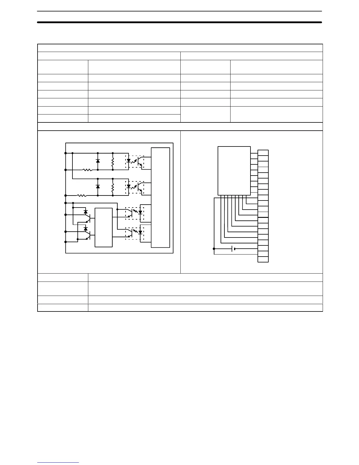
Circuit Configuration
16
17
18
19
NC
0
1
2
3
4
5
6
7
8
9
10
11
12
13
14
15
+
24 VDC
A
DATA
0
DATA 1
DATA 2
DATA 3
DATA 4
DATA 5
DATA 6
DATA 7
COM (24 V)
STB 0
STB 1
STB 2
STB 3
STB 4
STB 5
STB 6
STB 7
COM (0 V)
24 V
Terminal Connections
Refer
to p
116 for connections.
No. of Inputs 64, dynamic
Internal Current
Consumption
300 mA, 5 VDC max.
Weight 450 grams max.
Dimensions A-shape
Wiring Dynamic Inputs
When
a large number of bits must be controlled, an ID212 DC Input Unit can simplify wiring by inputting status to up
to
64 bits through only 16 points. Using digital switches or a specially wired keyboard, the dif
ferent combinations of
input
points will determine which bits are ON. T
wo examples of connections using digital switches or a keyboard
are given.

 Loading...


