37
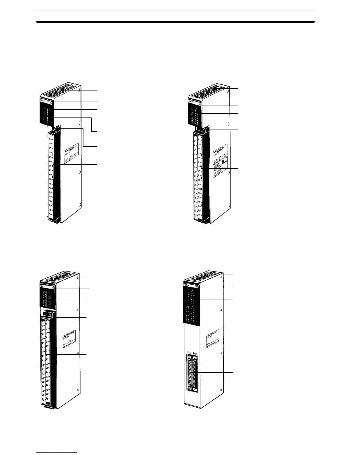
2-3-6 I/O Units
I/O Units come in 5 shapes; A-shape, B-shape, C-shape, D-shape, and
E-shape.
Refer to
Appendix B Specifications
for the dimensions of each I/O Unit.
Mounting screw
Provided at top and bottom.
Nameplate
Fuse blowout alarm indicator
Provided on OD411/OA121/
OA222/OA223.
I/O indicators
Indicate ON/OFF status.
Terminal block mounting screw
Provided at top and bottom.
20-terminal terminal block
Removable.
A-shape
Mounting screw
Provided at top and bottom.
Nameplate
I/O indicators
Indicate ON/OFF status.
Terminal block mounting screw
Provided at top and bottom.
38-terminal terminal block
Removable.
B-shape
Mounting screw
Provided at top and bottom.
Nameplate
I/O indicators
Indicate ON/OFF status.
Terminal block mounting screw
Provided at top and bottom.
38-terminal terminal block
Removable.
C-shape
Mounting screw
Provided at top and bottom.
Nameplate
I/O indicators
Indicate ON/OFF status.
Two 40-terminal terminal
block connectors
Removable.
D-shape
Rack Components Section 2-3

 Loading...


