41
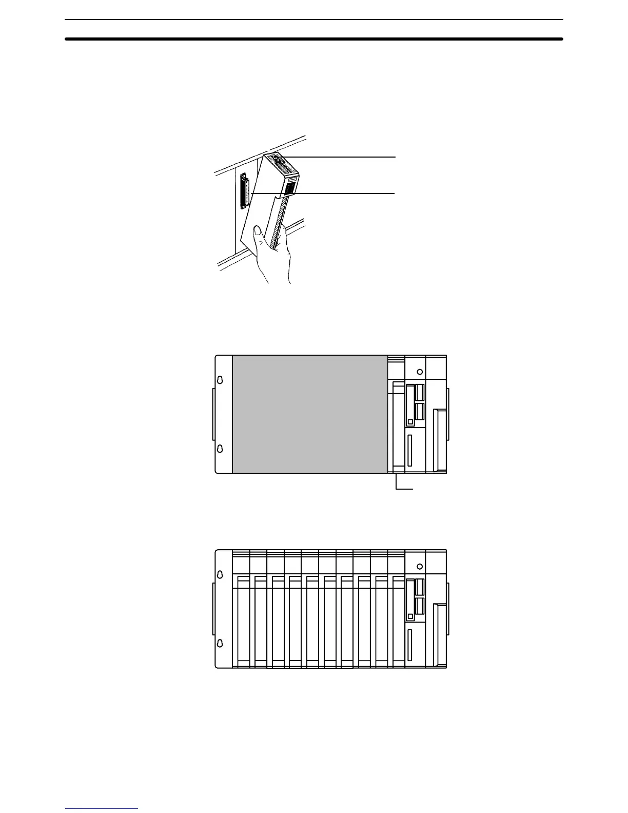
The
CV
-series CPUs have no I/O points built in. In order to complete
the PC we
need
to mount one or
more Units providing I/O points to the Backplane. Mount
the
Units to the Backplane by pressing them firmly into position, making sure
the
connectors are properly mated. Secure the Unit by tightening the mounting
screws located on the top and bottom of the Unit.
Mounting screws
Provided at the top and
bottom of the Unit.
Connector
Make sure the connectors
are properly mated.
The
following figure shows
one I/O Unit mounted directly to the left of the CPU.
Units other than the Power Supply Unit, the CPU, and the I/O Control Unit (see
below) can be mounted to any of the other slots on the CPU Rack.
I/O
Unit
As
you can see from the figure, there is still some space available to the left of the
I/O Unit. This space is for any additional Units that may be required.
The
figure above shows
a total of ten I/O Units mounted to the Backplane. These
I/O
Units could be replaced by other Units, such as Special I/O Units, CPU Bus
Units,
etc. I/O Units come in five shapes; A-, B-, C-, D- and E-shape (refer to
Ap-
pendix
B Specifications
) each of which can be mounted to any of the ten slots.
The
Backplane, Power Supply Unit, CPU, and other Units are collectively called
a CPU Rack.
Assembly Section 3-1

 Loading...


