42
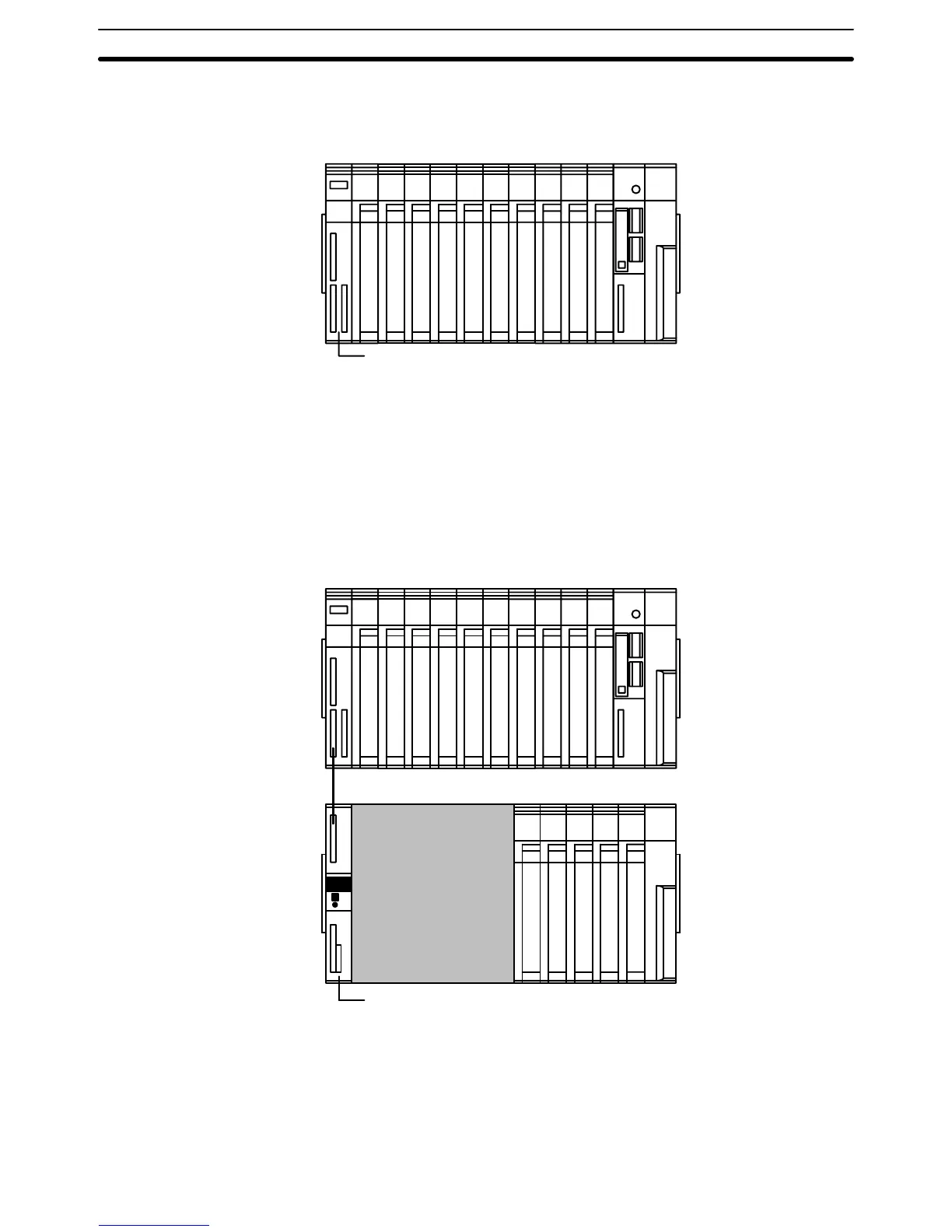
If we want to include more than ten Units in our configuration, we can add an
additional
Rack by mounting an I/O Control Unit
to the leftmost slot of the CPU
Rack.
I/O
Control Unit
Now
we can use a cable to connect the CPU Rack to another Rack. This Rack
has
a Power Supply Unit and I/O Units mounted to it, but it has no CPU of its own.
The
additional Rack must also have an I/O Interface Unit mounted to its leftmost
slot
to allow communications between the additional Rack and
the CPU Rack.
The
Backplane, Power Supply Unit, I/O Interface Unit, and other Units are col
-
lective called an Expansion I/O Rack or an Expansion CPU Rack. The differ-
ences
between the various types of Rack and the types of Systems they can be
used in are
described in earlier sections of this manual. A CPU Rack connected
to a single Expansion I/O Rack is shown below.
I/O
Interface Unit
CPU Rack
Expansion I/O Rack
The
CPU Rack and Expansion I/O Rack shown above are connected by a cable
via
the I/O Control Unit and I/O Interface Unit. It is possible to keep adding Ex
-
pansion I/O Racks in this way until the maximum number of I/O points for the
system
is reached. Each Expansion I/O Rack requires an I/O Interface Unit, al
-
though
a single Expansion I/O Rack can be connected by directly connecting
the
CPU and Expansion I/O Backplanes, as described in an earlier section.
Assembly Section 3-1

 Loading...


