48
The
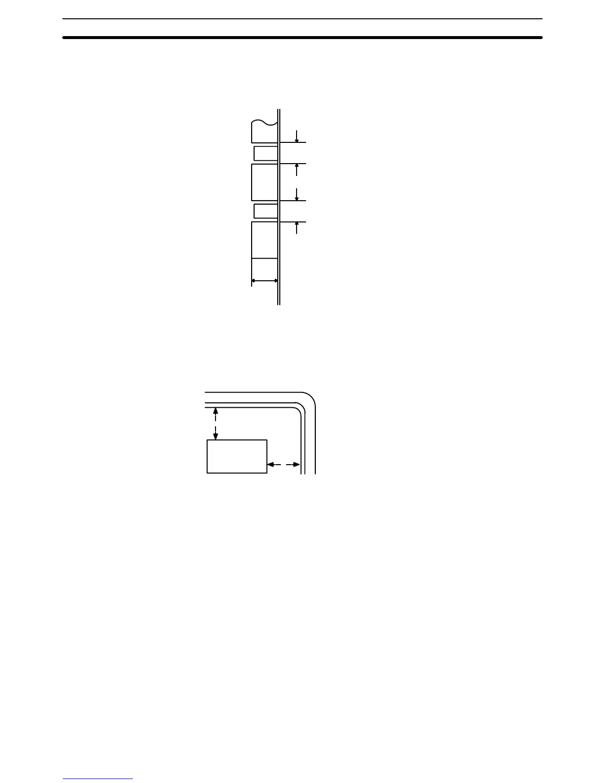
following figure shows a side view of a mounted CPU and two Expansion I/O
Racks. There should be a distance of 70 to 120 mm between the Racks. The
total length of I/O cables connecting any one series of Expansion I/O Racks
must be 50 m or less.
CPU
Duct
I/O
Approx. 100 mm
Duct
I/O
70 to 120 mm
70 to 120 mm
Do not mount the PC in a control panel in which high-power equipment is in-
stalled
and make
sure the point of installation is at least 200 mm away from pow
-
er
lines as shown in the following diagram. Ensure
the plate to which the PC is
mounted is grounded.
PC
200 mm min.
200 mm min.
Power lines
Mounting Racks Section 3-3

 Loading...


