!
!
51
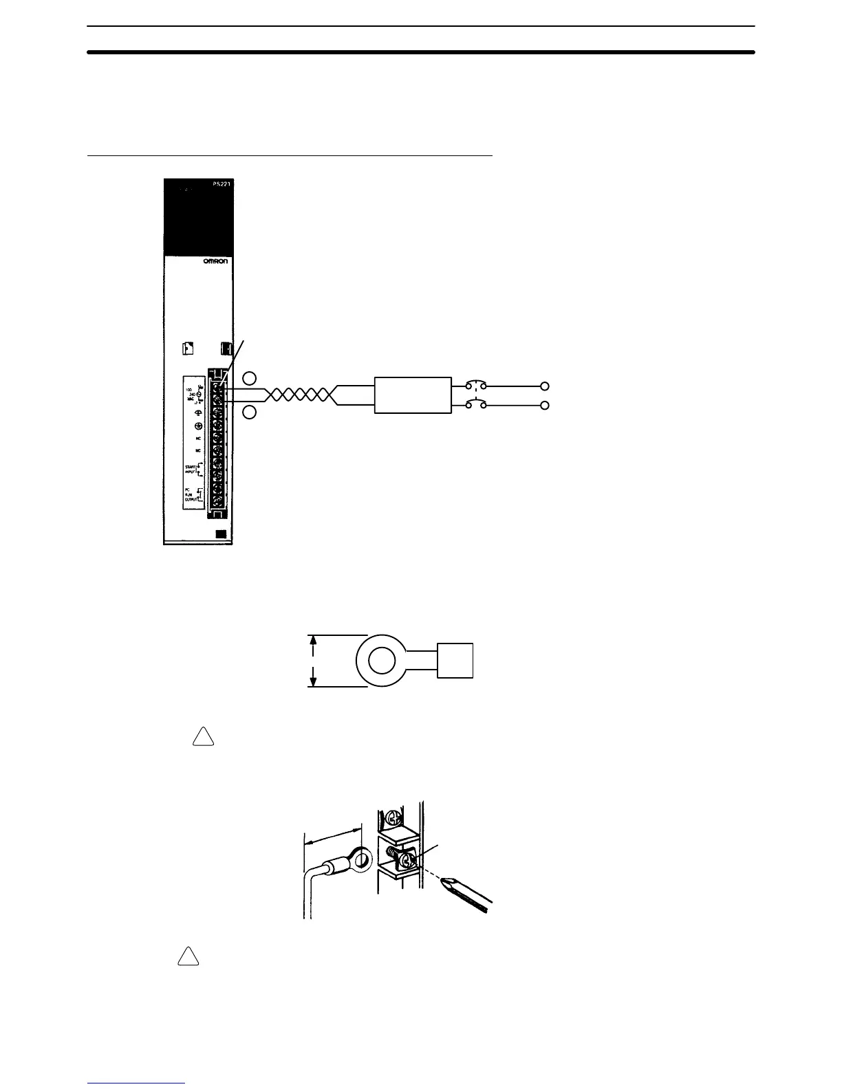
3-4-1 Wiring the Power Source
The
following diagrams show the proper way to connect the power source to the
Power Supply Unit. The terminals marked “NC” are not connected internally.
AC Power Supply Units: CV500-PS221/CVM1-PA208
1:1 isolation
transformer
Screw (3.5 mm head with
self-raising pressure plate)
Isolation transformer
•
Noise between the PC
and ground can be signif
-
icantly reduced by con
-
necting a 1-to-1 isolation
transformer
. Do not
ground the secondary
coil of the transformer
.
AC power source
•
Supply 100 to 120 or
200 to 240 V
AC
•
Keep voltage fluc
-
tuations within the spe
-
cified range (refer to
Appendix B Specifica
-
tions
)
Breaker
Power Line
• Use A
WG 14
twisted-pair cable
(cross-sectional
area: 2 mm
2
min.
Use
round crimp terminals for wiring. Do not connect bare stranded wires direct
-
ly to terminal blocks. Use M3.5 screws for tightening crimp terminals.
7
mm max.
Caution Tighten
the screws on the terminal block of the AC Power Supply Unit to a torque
of
0.8 N
S
m. The loose screws may result in short-circuit, burning, or malfunc
-
tion.
M3.5 screw
T
ightening torque: 0.8 N
S m
20 mm max.
WARNING Do
not allow your hands or any other part of your body
, or any object in
contact
with your body, to come into contact with the AC power supply section after
power
has been turned on. Contact
with the power supply section will result in a
dangerous or fatal electrical shock.
Power Supply Units Section 3-4

 Loading...


