Installation
Donottouchtheemitterand/orreceiverblockofthesensor.Fingerprint
depositsmayresultinimproperdetection.Ifaccidentallytouched,
pleasewipegentlywithadrycloth.Donotuseorganicsolvent(e.g.
paintthinnerandalcohol).
1
MountingoftheSensor
1-1
Mountingbracketsaresoldseparately.
Tighteningtorqueforthemountingholeis0.6N・morless(M3screw).
<Sizeofinstallationholes(Unit:mm)>
ConstraintsonSensorInstallation
1-2
ConnectionMethod
2-2
CordAllowableBendingRadius
2-3
■Orientationconsiderationsforinstallation
Connection
2
Input/OutputCircuitDiagram
2-1
Totalloadcurrentofthetwooutputroutesmustbe100mAorless.
Totalloadcurrentofthetwooutputroutesmustbe100mAorless.
(Detectionclosetoawall) <Detectioninahole>
<Detectingaworkpiecewithastep>
Stabledetectionis
availableevenforthe
leveldifferencepart.
Abnormaldetection
valuemayappearatthe
leveldifferencepart.
Detectionisnot
possibleiftheemitter
and/orreceiveris
blocked.
■UsingPin2(whitewire)asexternalinput"3-3ExternalInput"(page3).
①
④
②
③
+V
OUT1
OUT2
0V
Brown
Black
White
Blue
Brown
Black
White
Blue
Brown
Black
White
Blue
Brown
Black
White
Blue
Brown
Black
White
Blue
Load
NPN
Model
Outputmethod
Input/Outputcircuitdiagram
E3AS-
□□N□
10to30VDC
10to30VDC
10to30VDC
10to30VDC
①
④
②
③
+V
OUT1
OUT2
0V
PNP/COM□
StandardI/O
Mode
①
④
②
③
①
④
②
③
+V
C/Q
DO
0V
+V
C/Q
DI/DO
0V
IO-LinkMaster
PNP/COM□
IO-LinkMode
E3AS-
□□D□
or
E3AS-
□□T□
Load
Load Load
NPN
Model Method Input/Outputcircuitdiagram
E3AS-
□□N□
PNP/COM□
StandardI/O
Mode
PNP/COM□
IO-LinkMode
E3AS-
□□D□
or
E3AS-
□□T□
TheextensionofthecordunderthestandardI/Omodeshouldbe100mor
less.TheextensionofthecordintheIO-Linkmodeshouldbe20morless.
Pre-wiredModels
M12SmartclickConnectorModel
M8ConnectorModel
E3AS-HL□□ □M
E3AS-HL□□M3
M8ConnectorModels
E3AS-HL□□-M1TJ
E3AS-HL□□-M3J
Brown
Black
White
Blue
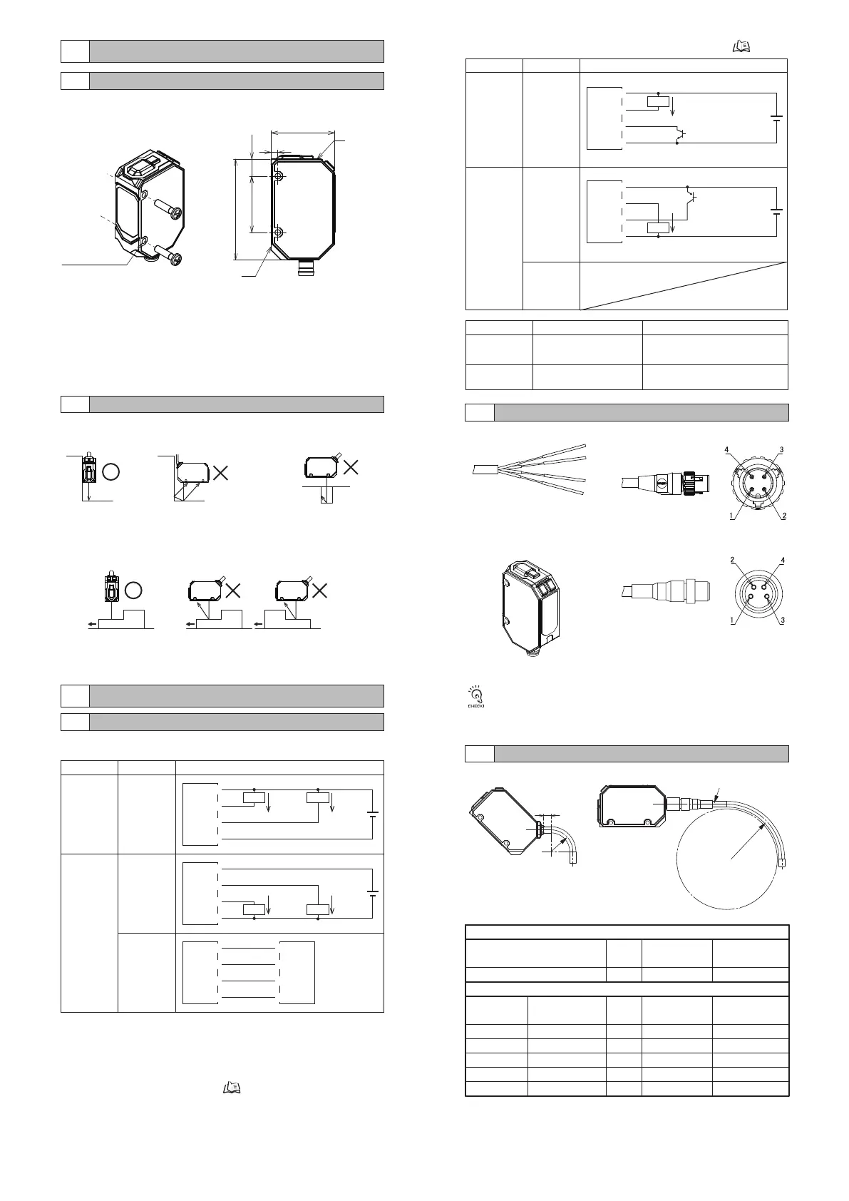
BendingforPre-wiredandConnectorModels
Cablespec.
PVCcable
BendingofsensorI/Oconnectorcord
Model
XS3F-M8PVC
XS2F/W-D4-F
XS5F/W-D4-F
XS5F/W-D4-X
XS5F/W-D4-XR
External
diameter
Φ4
External
diameter
Φ5
Φ6
Φ6
Φ6
Φ6
Cable
Materialspec.
PVC
Incombustiblerobot
Incombustiblerobot
Highlyoil-resistantPVC
Highlyoil-resistantrobotPVC
Lengthnotallowed
tobend:mm
5
Lengthnotallowed
tobend:mm
0
0
0
0
0
Minimumbending
radius:mm
13
Minimumbending
radius:mm
36
40
40
40
40
Reference
surface
Referencesurface
2-M3×P0.5
Throughhole
25.4
45.5
7.7
3
28.7
■UsingPin2(whitewire)asoutput
Note1.ThestandardI/OmodeisusedasPNPON/OFFoutput.
Note2.TheIO-LinkmodeisusedforcommunicationswiththeIO-Linkmaster.
TheC/QisusedforIO-Linkcommunications.ThesensoroutputDOis
usedforON/OFFoutput.
Note3.Fordetailedinformationonmodels,ratings,andperformance,referto
"8RatingsandSpecifications"(page12).
Externalinput NPN
PNP
ONtime
OFFtime
①
④
②
③
+V
OUT1
EXTIN
0V
Load
①
④
②
③
+V
OUT1
EXTIN
0V
Load
100mAorless
100mAorless
ExternalInput
ExternalInput
0Vshort-circuitor1.5Vorless
Powersupplyvoltage
short-circuitoropen
Powersupplyvoltageshort-circuitor
withinpowersupplyvoltage-1.5V
0Vshort-circuitoropen
(AWG24,insulatorΦ1.05)
Lengthnot
allowedtobend:
5mm
Minimumbendingradius
R13mm
Lengthnotallowedtobend
Minimumbendingradius
2
Lesssusceptible
tostraylight.
Susceptibletostraylight,
andthedetectedvalue
mayvary.

 Loading...