F3W-E
5
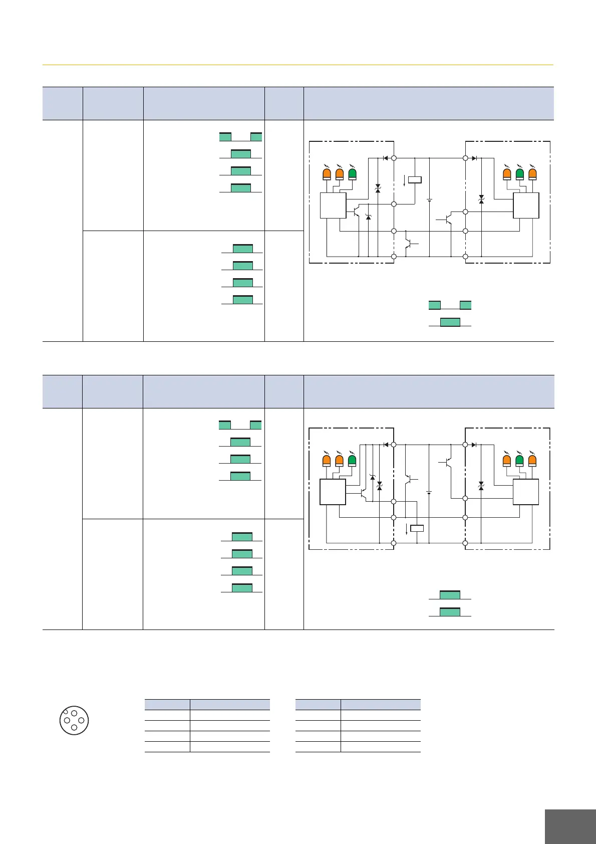
I/O Circuits
NPN Open-collector Outputs
Note: The emission stop input cannot be used with pre-wired connector models.
PNP Open-collector Outputs
Note: The emission stop input cannot be used with pre-wired connector models.
Connector Pin Arrangement
NPN/PNP Open Collector Outputs
F3W-E032B6/B8
Model
Operation
mode
Timing chart
Mode
selector
switch
Output circuit
F3W
-E032A6
F3W
-E032B6
Dark-ON mode
ON:
One beam
or more is
interrupted
OFF:
No beam is
interrupted
Note: The control output will turn ON
if the emission stop input is
received.
D-ON
(DARK
ON)
The following figure gives the relation between the picking instruc-
tion input and the picking indicators.
Light-ON
mode
ON:
No beam is
interrupted
OFF:
One beam
or more is
interrupted
Note: The control output will turn
OFF if the emission stop input
is received.
L-ON
(LIGHT
ON)
Model
Operation
mode
Timing chart
Mode
selector
switch
Output circuit
F3W
-E032A8
F3W
-E032B8
Dark-ON
mode
ON:
One beam
or more is
interrupted
OFF:
No beam is
interrupted
Note: The control output will turn ON
if the emission stop input is
received.
D-ON
(DARK
ON)
The following figure gives the relation between the picking instruc-
tion input and the picking indicators.
Light-ON
mode
ON:
No beam is
interrupted
OFF:
One beam
or more is
interrupted
Note: The control output will turn
OFF if the emission stop input
is received.
L-ON
(LIGHT
ON)
No beam is interrupted
One beam or more is interrupted
ON
OFF
ON
OFF
Operate
Reset
Operation indicator
(orange)
Light
incident
Control output
Load (e.g., relay)
Picking
indicators
(12 orange
indicators)
Operation
indicator
(orange)
Stability
indicator
(green)
Receiver
main
circuit
Receiver Emitter
Picking
indicators
(12 orange
indicators)
Power
indicator
(green)
Emission
stop
indicator
(orange)
Emitter
main
circuit
12 to
24 VDC
Picking
instruction
input
Emission
stop input
(See note.)
Brown
Pink
Black
Blue
Brown
Pink
Black
Blue
Load
Load current:
100 mA
max.
+DC
0 V
Open
0 V
ON
OFF
Picking indicators (orange)
Picking instruction input
No beam is interrupted
One beam or more is interrupted
ON
OFF
ON
OFF
Operate
Reset
Operation indicator
(orange)
Light
incident
Control output
Load (e.g., relay)
No beam is interrupted
One beam or more is interrupted
ON
OFF
ON
OFF
Operate
Reset
Operation indicator
(orange)
Light
incident
Control output
Load (e.g., relay)
Load current:
100 mA max.
Picking
indicators
(12 orange
indicators)
Operation
indicator
(orange)
Stability
indicator
(green)
Receiver
main
circuit
Receiver Emitter
Picking
indicators
(12 orange
indicators)
Power
indicator
(green)
Emission
stop
indicator
(orange)
Emitter
main
circuit
12 to
24 VDC
Picking
instruction
input
Emission
stop input
(See note.)
Brown
Pink
Black
Blue
Brown
Pink
Black
Blue
Load
+DC
0 V
Power supply voltage
Open
ON
OFF
Picking indicators (orange)
Picking instruction input
No beam is interrupted
One beam or more is interrupted
ON
OFF
ON
OFF
Operate
Reset
Operation indicator
(orange)
Light
incident
Control output
Load (e.g., relay)
3
1
2
4
Receiver Emitter
Pin number Specification
1+V
2 Picking instruction input
30 V
4 Control output
Pin number Specification
1+V
2 Picking instruction input
30 V
4 Open
 Loading...