EasyManua.ls Logo

Omron E3NX-CA21 2M - User Manual

Omron E3NX-CA21 2M
174 pages
To Next Page IconTo Next Page
Loading...
E3NW-ECT
EtherCAT®
Digital Sensor Communication Unit
Operation Manual
E429-E1-10
Authorized Distributor:
In the interest of product improvement,
specifications are subject to change without notice.
Cat. No. E429-E1-10
0220
© OMRON Corporation 2013-2019 All Rights Reserved.
OMRON Corporation Industrial Automation Company
OMRON ELECTRONICS LLC
2895 Greenspoint Parkway, Suite 200
Hoffman Estates, IL 60169 U.S.A.
Tel: (1) 847-843-7900/Fax: (1) 847-843-7787
Contact: www.ia.omron.com
Kyoto, JAPAN
OMRON ASIA PACIFIC PTE. LTD.
No. 438A Alexandra Road # 05-05/08 (Lobby 2),
Alexandra Technopark,
Singapore 119967
Tel: (65) 6835-3011/Fax: (65) 6835-2711
OMRON (CHINA) CO., LTD.
Room 2211, Bank of China Tower,
200 Yin Cheng Zhong Road,
PuDong New Area, Shanghai, 200120, China
Tel: (86) 21-5037-2222/Fax: (86) 21-5037-2200
Regional Headquarters
OMRON EUROPE B.V.
Sensor Business Unit
Carl-Benz-Str. 4, D-71154 Nufringen, Germany
Tel: (49) 7032-811-0/Fax: (49) 7032-811-199

Table of Contents

Question and Answer IconNeed help?

Do you have a question about the Omron E3NX-CA21 2M and is the answer not in the manual?

Omron E3NX-CA21 2M Specifications

General IconGeneral
TypeFiber Amplifier Unit
ModelE3NX-CA21 2M
Sensing MethodThrough-beam
Compatible AmplifiersE3NX series
Output TypeNPN
Light SourceRed LED
Operating Temperature-25 to 55°C
Cable Length2 m
Supply Voltage12-24 VDC
Connection MethodCable
Protection CircuitReverse polarity protection
Connector TypeN/A (Fiber head only)

Summary

Structure of This Manual

Chapter 1 EtherCAT Network

Explains EtherCAT features and network configuration.

Chapter 2 EtherCAT Sensor Communication Unit

Overviews the E3NW-ECT unit and its types.

Chapter 3 Basic Usage Procedures

Explains setup and usage procedures with examples.

Chapter 4 Installation and Wiring

Details how to install and wire units and the network.

Chapter 5 EtherCAT Communications

Explains the details of EtherCAT communications.

Chapter 6 E3 NW-ECT Hardware specifications

Details the hardware specifications of the E3NW-ECT.

Chapter 7 E3 NW-ECT Functional specifications

Details the functional specifications of the E3NW-ECT.

Chapter 8 Troubleshooting and Maintenance

Provides methods for troubleshooting and equipment maintenance.

Safety Precautions

Precautions for Safe Use

1 EtherCAT Network

2 EtherCAT Sensor Communication Unit

2-1 Overview of E3 NW-ECT

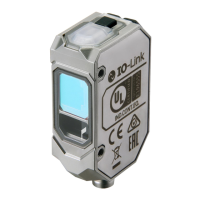
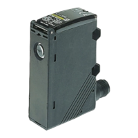
Provides an overview of the E3NW-ECT unit and its features.

2-2 Connectable Sensor Amplifiers

Lists and describes the sensor amplifiers connectable to the E3NW-ECT.

3 Basic Usage Procedures

3-2 Setting and Wiring Hardware

Details how to set up and wire the EtherCAT master and slave units.

3-3 Starting Communications

Guides on starting the system and establishing EtherCAT communications.

3-4 Checking Operations

Explains how to check unit displays and confirm I/O data.

4 Installation and Wiring

4-1 Mounting E3 NW-ECT and Sensor Amplifiers

Describes how to mount and remove the E3NW-ECT and sensor amplifiers.

4-2 Connecting to EtherCAT Network

Explains how to lay down and connect the EtherCAT network cables.

4-3 Connecting to Unit Power Supply and I;O Power Supply

Details how to connect the unit power supply and I/O power supply.

5 EtherCAT Communications

5-3 Communications State Transitions

Illustrates the state transition model of EtherCAT Slave Unit communications.

5-4 Process Data Objects (PDO)

Details Process Data Objects (PDOs) for real-time data transfer.

5-5 Service Data Object (SDO)

Explains Service Data Objects (SDOs) for parameter settings and monitoring.

5-6 EtherCAT Master Unit - Slave Unit Communications

Describes the communication modes between master and slave units.

5-7 Emergency Messages

Covers how the unit notifies emergency messages to the master unit.

6 Hardware Specifications of E3 NW-ECT

6-1 EtherCAT Communications Specifications

Details the EtherCAT communication specifications of the slave unit.

6-3 Hardware Specifications

Details the hardware specifications, including indicators and connectors.

7 Function Specifications

7-2 Functions of E3 NW-ECT

Describes convenient functions of the Digital I/O Slave Units.

8 Troubleshooting and Maintenance

8-1 Troubleshooting

Lists errors that can be checked with status indicators and actions to take.

8-2 Equipment Maintenance

Describes routine equipment maintenance, including cleaning and inspections.

Related product manuals