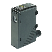
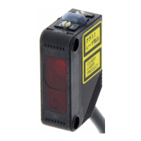
E3S-A
I/O Circuit Diagrams
NPN Output
Diffuse-reflective Sensor Diffuse-reflective Sensor Sensing Object Size vs. Sensing
Distance
E3S-AD@1/AD@2/AD@3/AD@6/AD@7/
AD@8 (Detection of White Paper)
E3S-AD@1/AD@2/AD@3/AD@6/AD@7/
AD@8 (Detection of Black Paper)
E3S-AD@1/AD@2/AD@3/AD@6/AD@7/
AD@8
Model
Operation
mode
Timing charts
Mode
selector
switch
Output circuit
E3S-AT11
E3S-AT16
E3S-AT61
E3S-AT66
E3S-AR11
E3S-AR16
E3S-AR61
E3S-AR66
E3S-AD11
E3S-AD16
E3S-AD61
E3S-AD66
E3S-AD12
E3S-AD17
E3S-AD62
E3S-AD67
E3S-AD13
E3S-AD18
E3S-AD63
E3S-AD68
Light-ON
L Side
(LIGHT ON)
Through-beam Receivers, Retro-reflective Sensors, Diffuse-reflective
Sensors
Dark-ON
D Side
(DARK ON)
Through-beam Emitters
500
300
100
50
30
10
5
3
1
0.5
0 0.2 0.4 0.6 0.8 1 1.2
E3S-AD@3/@8
E3S-AD@2/@7
E3S
-AD@1/@6
Oper-
ating
level
Distance (m)
Sensing object: White paper
E3S-AD
@1/@3/@6/@8: 100 × 100 mm
E3S-AD
@2/@7: 200 × 200 mm
Excess gain ratio (times)
100
50
30
10
5
3
1
0.5
0.3
0.1
0 200 400 600 800
E3S-AD@3/@8
E3S-AD@2/@7
E3S
-AD@1/@6
Oper-
ating
level
Distance (mm)
Sensing object: Black paper
E3S-AD
@1/@3/@6/@8: 100 × 100 mm
E3S-AD
@2/@7: 200 × 200 mm
Excess gain ratio (times)
1.2
1
0.8
0.6
0.4
0.2
0
Side of object (mm)
50 × 50 100 × 100 200 × 200 300 × 300
E3S-AD@1/@6
E3S-AD@3/@8
OFF
ON
OFF
ON
OFF
ON
E3S-AD@2/@7
Sensing object: white paper
Distance (m)
Incident light
No incident light
ON
OFF
ON
OFF
Operate
Reset
Light indicator
(red)
(Between brown and black)
Output
transistor
Load
(e.g., relay)
Connector Pin Arrangement
Note: Pin 2 is not used.
1
3
4
Light
indi-
cator
Stability
indicator
Photo-
electric
Sensor
main
circuit
Z
D
Load
Brown
Blue
Black
(Control
output)
(Relay)
100 mA max.
10 to
30 VDC
(red)
(green)
3
1
2
4
Incident light
No incident light
ON
OFF
ON
OFF
Operate
Reset
Light indicator
(red)
(Between brown and black)
Output
transistor
Load
(e.g., relay)
Connector Pin Arrangement
Note: Pins 2 and 4 are not used.
3
1
Power
indica-
tor
Photo-
electric
Sensor
main
circuit
Brown
Blue
10 to
30 VDC
(red)
3
1
2
4
http://www.ia.omron.com/
6
(c)Copyright OMRON Corporation 2008 All Rights Reserved.