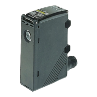
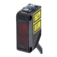
The E3S-A is a series of built-in amplifier photoelectric sensors designed for various industrial sensing applications. These sensors are available in medium size and offer both red light and infrared light options. The series includes through-beam, retro-reflective, and diffuse-reflective sensing methods, catering to a wide range of detection needs.
Function Description
The E3S-A sensors operate by emitting light and detecting its reflection or interruption to sense objects. They feature a built-in amplifier, simplifying integration into control systems. Depending on the model, they offer NPN or PNP output types.
Several models incorporate advanced functions such as a timer, turbo mode, and external self-diagnosis. The timer function provides an OFF-delay, adjustable from 0 to 100 ms, allowing for flexible control of output timing. The turbo function, available on some emitter models, increases the intensity of the red LED light source, making the light spot more visible for easier optical axis checking, especially at longer distances. External diagnostic inputs are also available on some models, providing additional monitoring capabilities.
The sensors support both Light-ON and Dark-ON operation modes, which can be selected via a mode selector switch on the receiver. For through-beam and retro-reflective sensors, the default operating mode is Dark-ON, while for diffuse-reflective sensors, it is Light-ON.
Important Technical Specifications
- Sensing Distance:
- Through-beam: 7 m
- Retro-reflective: 2 m (with E39-R1 reflector, minimum required distance 100 mm)
- Diffuse-reflective: 100 mm (wide view), 200 mm, 700 mm
- Standard Sensing Object:
- Through-beam: Opaque, 10-mm diameter min.
- Retro-reflective: Opaque, 75-mm diameter min.
- Diffuse-reflective: White paper (100 x 100 mm for 100 mm/200 mm models, 200 x 200 mm for 700 mm models)
- Light Source (Wavelength):
- Through-beam and some diffuse-reflective: Red LED (700 nm)
- Retro-reflective and some diffuse-reflective: Infrared LED (880 nm)
- Power Supply Voltage: 10 to 30 VDC (including ripple (p-p) 10%)
- Current Consumption:
- Through-beam and Retro-reflective: 20 mA max. (plus approx. 15 mA with turbo function)
- Diffuse-reflective: 35 mA max. (30 mA max. plus approx. 15 mA with turbo function for some models)
- Control Output: Load power supply voltage: 30 VDC max., Load current: 100 mA max. (residual voltage: 1 V max.), Open-collector output (NPN or PNP depending on model), Light-ON/Dark-ON selectable.
- Self-diagnostic Output (for models with self-diagnostic outputs): Load power supply voltage: 30 VDC max., Load current: 50 mA max. (residual voltage: 1 V max.), Open-collector output (NPN or PNP depending on model).
- Response Time: 0.5 ms max.
- Protection Circuits: Power supply reverse polarity protection, Output short-circuit protection, Mutual interference prevention.
- Sensitivity Adjustment: Two-turn endless adjuster with an indicator.
- Ambient Illumination (Receiver side): Incandescent lamp: 5,000 lx max., Sunlight: 10,000 lx max.
- Ambient Temperature: Operating: -25°C to 55°C (with no icing or condensation), Storage: -40°C to 70°C (with no icing or condensation).
- Ambient Humidity: Operating: 35% to 85% (with no condensation), Storage: 35% to 95% (with no condensation).
- Degree of Protection: IEC IP67; NEMA: 4X (indoors only).
- Material: Case: PBT, Lens: Denatured polyallylate, Mounting Bracket: Stainless steel (SUS304).
Usage Features
- Connection Methods: Available with pre-wired cables (standard length 2 m) or M12 connectors, offering flexibility in installation.
- Mounting: The sensors come with a mounting bracket (E39-L69 for horizontal, E39-L70 for vertical) that aligns the optical axis with the machine axis when the mounting screw is inserted into the lock hole. This simplifies initial alignment. Protective covers (E39-L97 for horizontal, E39-L98 for vertical) are also available for enhanced protection.
- Optical Axis Adjustment: For through-beam models, the E3S-A incorporates two lenses. The lens in use is indicated by an arrow. When using slits (E39-S46, sold separately), they should be attached to the marked lens. The E39-R5 Optical Axis Confirmation Reflector (sold separately) can be used for precise optical axis alignment, especially over long distances.
- Sensitivity Adjustment: The sensitivity can be adjusted using a two-turn endless adjuster with an indicator. For diffuse-reflective sensors set to Light ON, a recommended procedure involves positioning the sensing object, adjusting sensitivity until the red LED turns ON (Position A), removing the object and adjusting until the red LED turns ON again (Position B), then counter-clockwise adjusting until the red LED turns OFF (Position C). The optimum sensitivity is typically halfway between A and C.
- Mutual Interference Prevention: For through-beam sensors, E39-E6 Polarized Mutual Interference Prevention Filters (sold separately) can be used. These filters, supplied in sets of four (two for emitters, two for receivers), help prevent mutual interference when multiple sensors are mounted in close proximity. The filters have arrows indicating polarization direction, and proper alignment (same direction for emitter and receiver) is crucial for functionality.
- Turbo Function: The turbo function, activated by pressing a switch, temporarily boosts the light intensity, making the red spot more visible for easier optical axis checking. It is recommended to use this function for short periods (max. 3 minutes) and to set the timer delay after checking the optical axis.
- Slits: E39-S46 insert-type long slits (sold separately) are available in various widths (0.5 mm, 1 mm, 2 mm) to reduce the minimum sensing object size. They are designed to fit into the rubber attachment with a metal cover.
Maintenance Features
- Troubleshooting: If the sensor does not operate, a checklist is provided, including verifying wiring, connections, mounting screw tightness, optical axis and sensitivity adjustments, sensing object characteristics, presence of foreign objects on lenses, and strong ambient light sources.
- Cleaning: The sensor's lens and case are primarily made of plastic. For cleaning, a soft, dry cloth should be used. Organic solvents, thinners, or other harsh chemicals should be avoided as they can damage the surface.
- Connector Handling: When using M8 or M12 connectors, ensure the sensor is turned OFF before connecting or disconnecting. The connector cover should be secured by hand, avoiding pliers, to prevent damage and maintain the degree of protection.
- Cable Management: The maximum recommended cable extension is 100 m with 0.3 mm² wire or greater. Cables should not be subjected to excessive tension (max. 30 N for <4 mm diameter, 50 N for ≥4 mm diameter) or repeated bending. It is also advised to separate sensor cables from high-voltage or power lines to prevent induction interference.
- Unused Leads: Unused leads for self-diagnosis or other special functions should be cut and wrapped with insulating tape to prevent contact with other terminals.