ATEG Automation GmbH
|
Intzestraße 50
|
42859 Remscheid
|
Germany
|
Tel.: +49 (0)2191 / 591457-0
|
info@ateg.de
|
www.ateg.de
Datenblatt
Lichtleiterverstärker E3X-HD
E3X-HD
E3X-HD
8
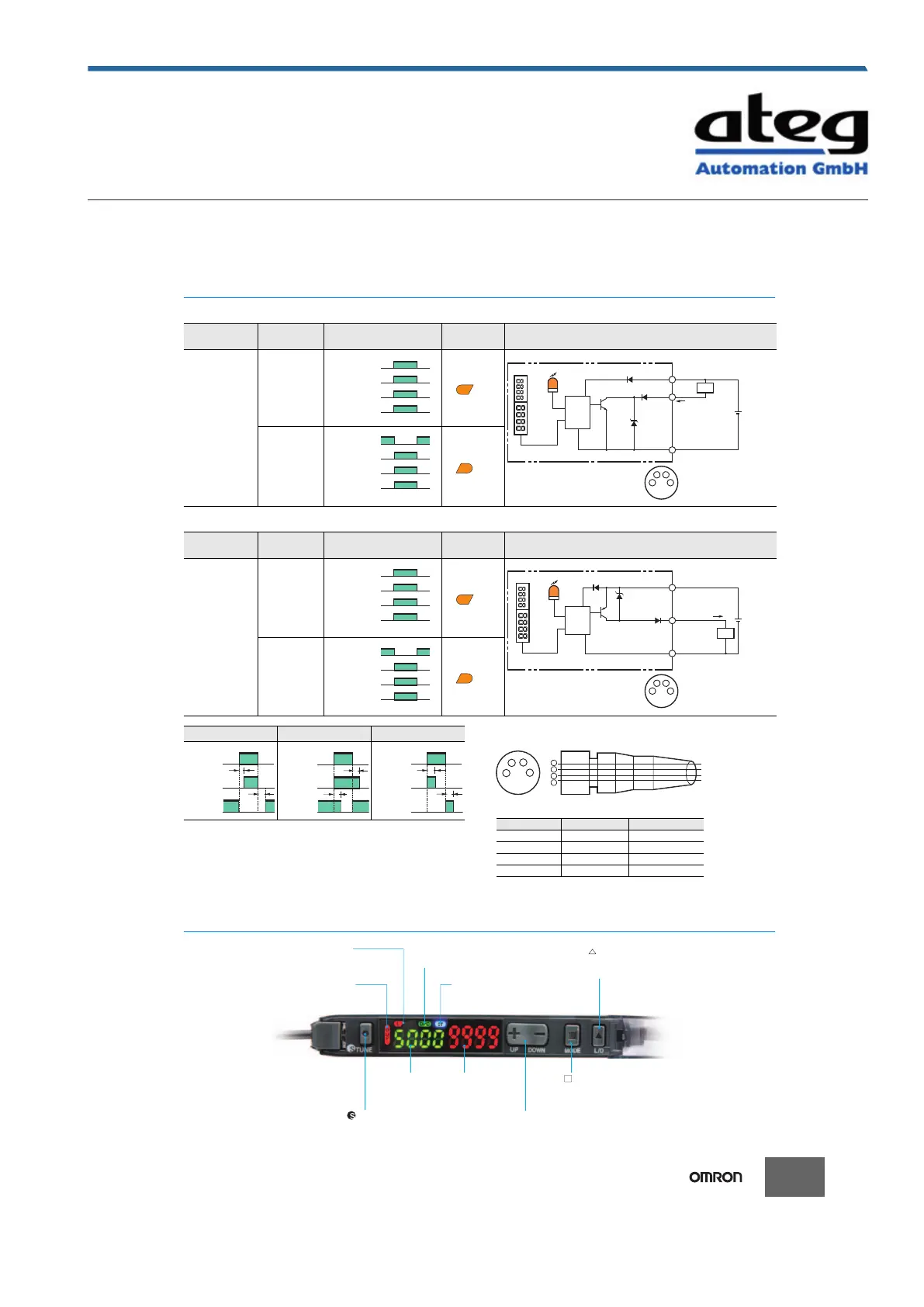
I/O Circuit Diagrams
NPN Output
PNP Output
Note: Timing Charts for Timer Settings (T: Set Time)
Plug (Sensor I/O Connector)
Nomenclature
Models
Operation
mode
Timing chart
L/D
indicators
Output circuit
E3X-HD11
E3X-HD6
E3X-HD14
Light-ON
Dark-ON
Incident light
No incident light
Lit
Not lit
ON
OFF
Set
Reset
OUT indicator
(orange)
Output
transistor
Load
(e.g., relay)
(Between blue and
black leads)
Photoelectric
Sensor main
circuit
Load
Brown
Control output
Black
Blue
12 to
24 VDC
OUT indicator (orange)
Display
• M8 Connector Pin Arrangement
Note: Pin 2 is not used.
1
2
4
3
1
4
3
Incident light
No incident light
Lit
Not lit
ON
OFF
Set
Reset
OUT indicator
(orange)
Output
transistor
Load
(e.g., relay)
(Between blue and
black leads)
Models
Operation
mode
Timing chart
L/D
indicators
Output circuit
E3X-HD41
E3X-HD8
E3X-HD44
Light-ON
Dark-ON
Incident light
No incident light
Lit
Not lit
ON
OFF
Set
Reset
OUT indicator
(orange)
Output
transistor
Load
(e.g., relay)
(Between blue and
black leads)
Photoelectric
Sensor main
circuit
Load
Control output
Brown
Black
Blue
12 to
24 VDC
OUT indicator (orange)
Display
• M8 Connector Pin Arrangement
Note: Pin 2 is not used.
1
2
4
3
1
4
3
Incident light
No incident light
Lit
Not lit
ON
OFF
Set
Reset
OUT indicator
(orange)
Output
transistor
Load
(e.g., relay)
(Between blue and
black leads)
ON delay OFF delay One-shot
Incident light
No incident light
ON
OFF
ON
OFF
Light-ON
Dark-ON
T
T
T
T
Incident light
No incident light
ON
OFF
ON
OFF
Light-ON
Dark-ON
T
T
Incident light
No incident light
ON
OFF
ON
OFF
Light-ON
Dark-ON
Note: Pin 2 is not used.
Wire color Connection pin Application
Brown 1 Power supply (+V)
White 2 ---
Blue 3 Power supply (0 V)
Black 4 Output
2
4
1
3
1
2
3
4
Brown
White
Blue
Black
Wire color
Terminal number
XS3F-M421-402-A
XS3F-M421-405-A
XS3F-M422-402-A
XS3F-M422-405-A
[L/D Indicator]
Indicates the setting status:
Light-ON (L) or Dark-ON (D).
[DPC Indicator]
Turns ON when Dynamic Power Control is effective.
[ L/D Button]
Use to switch between
Light-ON (L) and Dark-ON (D).
[OUT Indicator]
Turns ON when
the output is ON.
[ST Indicator]
Turns ON when Smart Tuning
is in progress.
Automatically sets the emitter
power and set values.
Threshold Level
Green digital display
Incident Level
Red digital display
[+−UP/DOWN Button]
Used to fine-tune the threshold
or change set values.
[ MODE Button]
Use to switch between Detection
Mode and Setting Mode.
[ TUNE Button]
Erstellt am 28.09.2020 um 20:20 Uhr | Alle Angaben ohne Gewähr, Irrtümer und Änderungen vorbehalten! Seite 9 von 14