Digital Position-Proportional Controllers E5EZ-PRR 49
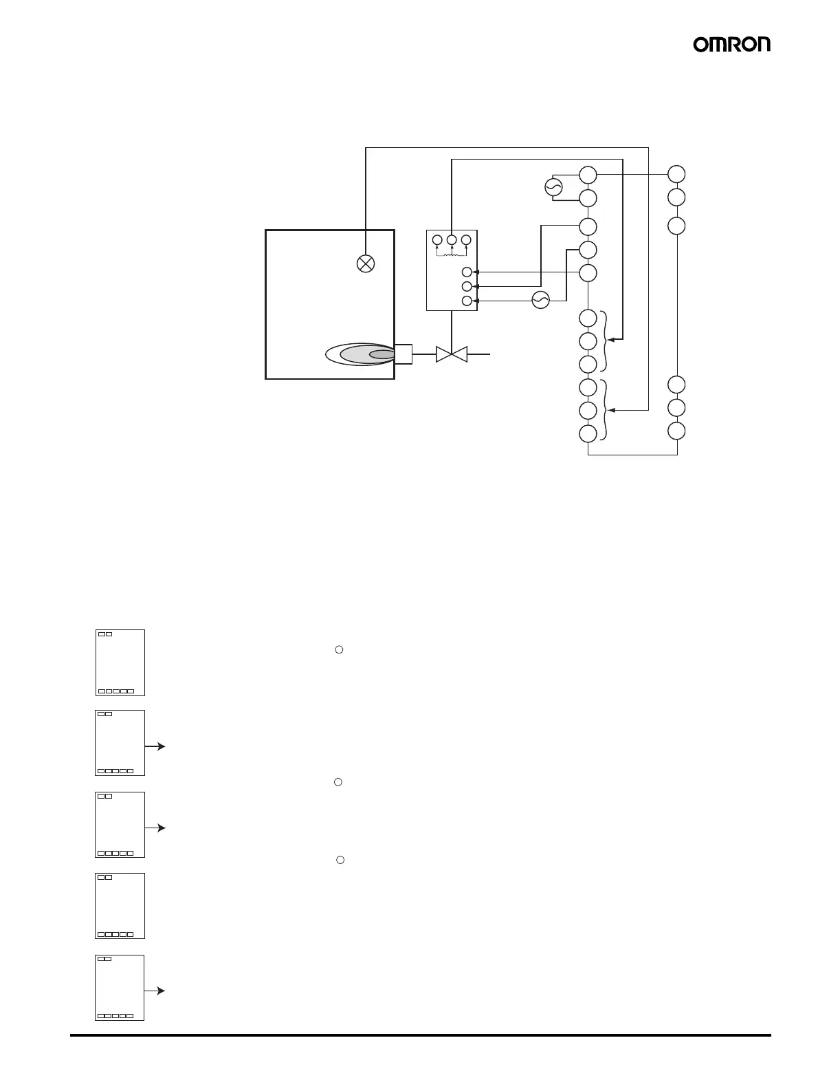
■ Wiring
Input should be connected to terminals 9, 10, and 11 depending upon input type. The Out 1 ter-
minal links to the position proportional valve's open side and the Out 2 terminal links to its closed
side.
■ Settings
Select a position proportional control model, and perform floating control using a position propor-
tional valve with a travel time (time from being totally open to being totally closed) of 45 seconds.
Then, use the SP ramp function to make gradual changes to the process value at rates of
10.0°C/ minute. The relevant data and content of the settings are as shown below:
Direct/ reverse operation = or-r: Reverse operation (initial value)
Closed/ floating = flot: Floating (initial value)
Trave l tim e =
45 seconds
SP ramp set values =
"10"
Here, the travel time and SP ramp values are set. Initial values are used for all others.
1. Press the
key for at least 3 seconds to switch from the operation level to the initial setting
level.
2. Press the M key multiple times, and select mot: travel time. Press the U key, making the set
value 45.
3. Press the
key for at least 1 second, returning to the operation level. The process value/ set
value/ percentage of valve opening will be displayed. Press the U key, setting the target
value as 250.
4. Press the
key for less than 1 second to switch from operation level to → adjustment level.
5. Press the M key multiple times, and select sprt: SP ramp set value. Press the U key, mak-
ing the set value 10.
1
2
3
4
5
6
7
8
9
10
11
12
13
14
20
21
22
CLOSE
OPEN
Valve
Position proportional valve
Ceramic kiln
(combustion)
Sensor
Burner
CWO
in-t
5
l.
ini
mot
30
l.
ini
45
Travel time
SP is the ramp’s
set value
Operation level
Adjustment level
1
0
sprt
0
l.
adj
U
U
U
25
100
.
0
0
25
0
at
l.
adj
off
Process value/ set value/
percentage of valve
opening
 Loading...


