E5EC/E5AC
22
*1 With set values 1, 4 and 5, the upper and lower limit values can be set
independently for each alarm type, and are expressed as “L” and “H.”
*2. Set value: 1, Upper- and lower-limit alarm
*3. Set value: 4, Upper- and lower-limit range
*4. Set value: 5, Upper- and lower-limit with standby sequence
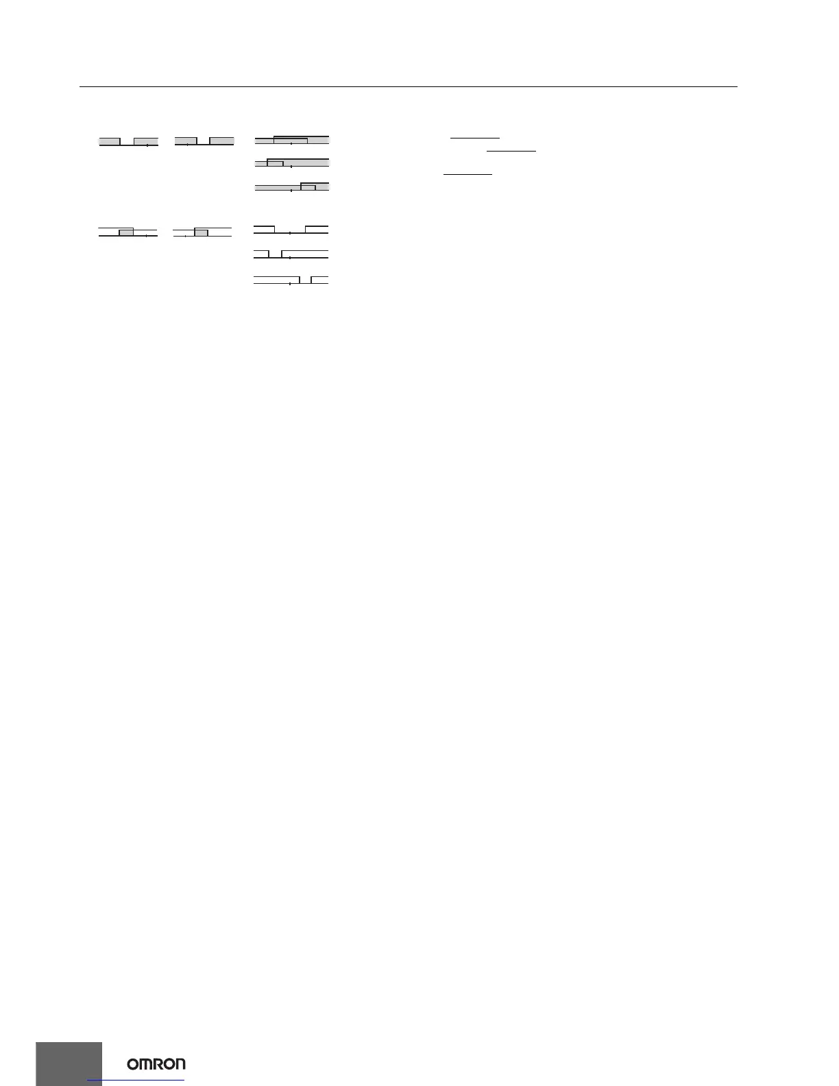
For Upper- and Lower-Limit Alarm Described Above *2
• Case 1 and 2
Always OFF
when the upper-limit and lower-limit hysteresis overlaps.
• Case 3: Always OFF
*5. Set value: 5, Upper- and lower-limit with standby sequence
Always OFF
when the upper-limit and lower-limit hysteresis overlaps.
*6. Refer to the E5
@
C Digital Temperature Controllers User's Manual (Cat. No.
H174) for information on the operation of the standby sequence.
*7. Refer to the E5
@
C Digital Temperature Controllers User's Manual (Cat. No.
H174) for information on the PV change rate alarm. This setting cannot be
used with a position-proportional model.
*8. Refer to the E5
@
C Digital Temperature Controllers User's Manual (Cat. No.
H174) for information on the PV change rate alarm.
*9. When heating/cooling control is performed, the MV absolute upper limit
alarm functions only for the heating operation and the MV absolute lower
limit alarm functions only for the cooling operation.
*10. This value is displayed only when a remote SP input is used. It functions in
both Local SP Mode and Remote SP Mode.
LHSP
Case 1
LHSP
Case 2
LHSP
LHSP
LHSP
Case 3 (Always ON)
H<0, L<0
H<0, L>0
|H| ≥ |L|
H>0, L<0
|H| ≤ |L|
H<0, L>0
|H| < |L|
H>0, L<0
|H| > |L|
LHSP
Case 1
LHSP
Case 2
LHSP
L
L
HSP
HSP
Case 3 (Always OFF)
H<0, L>0
|H| < |L|
H>0, L<0
|H| > |L|
H<0, L<0
H<0, L>0
|H| ≥ |L|
H>0, L<0
|H| ≤ |L|