2 - 45
2 Preparations
E5@C Digital Temperature Controllers User’s Manual (H174)
2-2 Using the Terminals
2
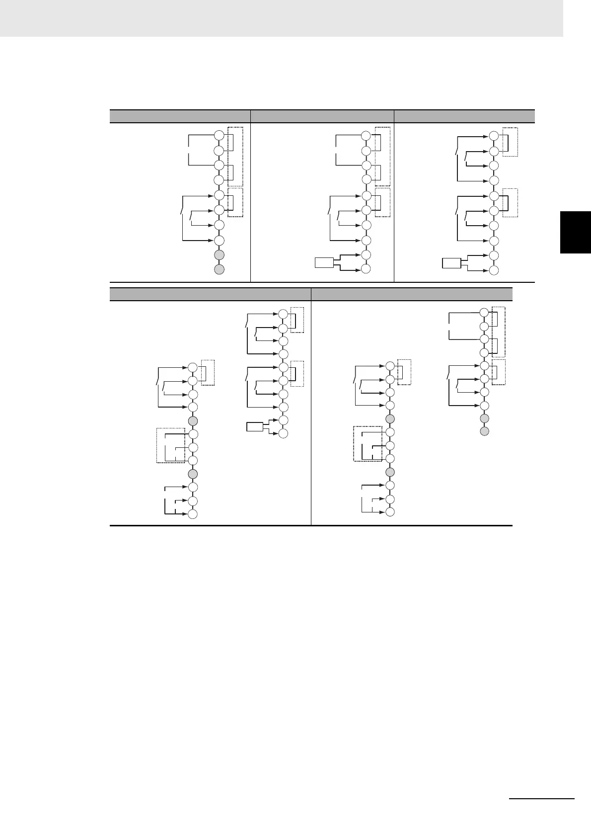
2-2-5 E5EC-B Terminal Block Wiring Example
Terminal Details
Do not connect anything to the terminals that are shaded gray.
* Common terminals are indicated with asterisks (*).
You can use communications common terminals for crossover wiring.
Note: Use non-voltage inputs for the event inputs.
The polarity for a non-contact input is indicated by “(-).”
004 008 010
011 14
RS-485
21
22
23
24
25
26
Communications
EV1
EV2
Event inputs
*
*
*
A(−)
B(+)
(−)
(−)
21
17
18
19
20
B(+)
A(−)
RS-485
Communications
CT1
CT
*
*
*
EV1
EV2
Event inputs
(−)
(−)
17
18
19
20
21
22
23
24
25
26
CT1
CT
*
*
EV1
EV2
Event inputs
(−)
(−)
EV3
EV4
Event inputs
(−)
(−)
17
18
19
20
21
22
23
24
25
26
+
+
−
−
V
mA
Transfer
output
Remote SP
input
+
+
-
I
V
CT1
CT
*
*
EV5
EV6
Event
inputs
(−)
EV3
EV4
Event inputs
(−)
(−)
EV1
EV2
Event
inputs
(−)
(−)
(−)
45
41
46
44
43
42
40
38
37
47
48
39
17
18
19
20
21
22
23
24
25
26
*
48
37
38
39
42
43
40
44
46
47
+
+
−
−
V
mA
+
+
−
I
V
41
45
Transfer
output
Remote SP
input
(−)
(−)
(−)
(−)
EV5
EV6
RS-485
21
22
23
24
25
26
EV1
EV2
Event
inputs
Event
inputs
*
*
*
Communications
B(+)
A(−)
*
20
19
18
17