Basic-type Digital Temperature Controller E5AN/E5EN 11
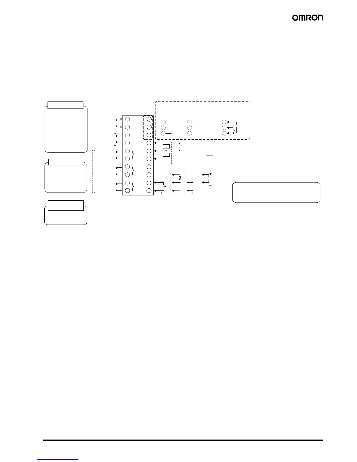
External Connections
• A voltage output (control output 1, for driving SSR) is not electrically insulated from the internal circuits. When using a grounding thermocouple,
do not connect any of the control output terminals to ground. If the control output terminals are connected to ground, errors will occur in the
measured temperature values as a result of leakage current.
The voltage output (control output 2, for driving SSR) has basic insulation provided for the internal circuit.
• Consult with your OMRON representative before using the external power supply for the ES1B for any other purpose.
A heater burnout alarm, heater short alarm,
heater overcurrent alarm, or input alarm is
sent to the output to which the alarm 1
function is assigned.
Communications
E53-EN03
RS-485
B (+)
11
A (−)
12
DO NOT USE
13
E53-EN01
RS-232C
SD
11
RD
12
SG
13
E53-AKB
Event inputs
11
12
13
250 VAC, 3 A
(resistive load)
Relay outputs
• 100 to 240 VAC
• 24 VAC/VDC (no polarity)
Current output
0 to 20 mA DC
Voltage output
(for driving SSR)
12 VDC, 40 mA
Load: 600 Ω max.
4 to 20 mA DC
Relay output
250 VAC, 5A
(resistive load)
Voltage output
(for driving SSR)
12 VDC, 21 mA
Long-life relay output
250 VAC, 3 A
(resistive load)
EV1
EV2
CT1/CT2
Control output 2
Auxiliary output
1, 2, 3
Control output 1
Input power supply
Auxiliary output 2
1
2
3
4
5
1 3
1 4
1 5
6
7
8
9
1 0
1 6
1 7
1 8
1 9
Control output 1
B
V
m A
Auxiliary output 3
2 0
C T 1
C T 2
+
-
Control output 2
D O N O T
U S E
+
-
External power supply
12 VDC, 20 mA
D O N O T
U S E
DO NOT USE
B
A
D O N O T
U S E
D O N O T
U S E
D O N O T
U S E
Auxiliary output 1
1 1
1 2
T/c Pt Volt mA
temperature analog
input input
Controllers
Option Units
 Loading...


