Com Data
for Modbus
6.1 Variable Area (Setting Range) List
6-13
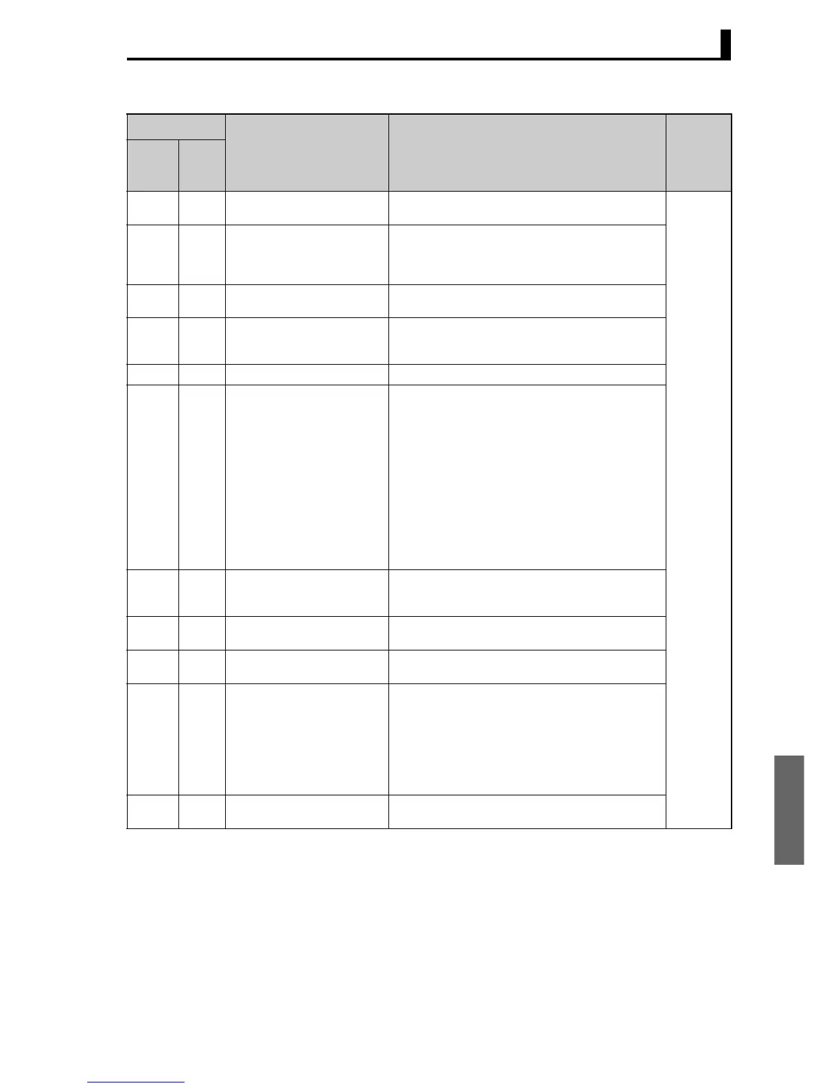
Address
Parameter name Setting (monitor) value LevelFour-
byte
mode
Two-
byte
mode
1006 3003 Automatic Display Return Time H'00000000 (0): OFF
H'00000001 to H'00000063 (1 to 99)
Advanced
function
setting
1008 3004 Display Refresh Period H'00000000 (0):OFF
H'00000001 (1): 0.25
H'00000002 (2): 0.5
H'00000003 (3): 1.0
1010 3008 Additional PV Display H'00000000 (0): OFF
H'00000001 (1): ON
1016 300B MV Display H'00000000 (0): OFF
(display of manipulated variable OFF)
H'00000001 (1): ON (display of manipulated variable ON)
1018 300C Move to Protect Level Time H'00000001 to H'0000001E (1 to 30)
101A 300D PV Change Color
H'00000000 (0): Orange
H'00000001 (1): Red
H'00000002 (2): Green
H'00000003 (3): Red to green: When ALM1 is ON
H'00000004 (4): Green to red: When ALM1 is ON
H'00000005 (5): Red to green to red: Within PV stable band:
Green
Outside stable band:
Red
H'00000006 (6): Green to orange to red: Within PV stable band:
Orange
Outside stable band:
Green, red
H'00000007 (7): Orange to green to red: Within PV stable band:
Green
Outside stable band:
Orange, red
101C 300E PV Stable Band H'00000001 to H'0000270F
(0.1 to 999.9 for TC/Pt universal input models)
(0.01 to 99.99 for Analog input models)
101E 300F Auto/Manual Select Addition H'00000000 (0): OFF
H'00000001 (1): ON
1020 3010 Character Select H'00000000 (0): OFF
H'00000001 (1): ON
1022 3011 PV Status Display Function H'00000000 (0):OFF
H'00000001 (1): Manual
H'00000002 (2): Stop
H'00000003 (3): Alarm 1
H'00000004 (4): Alarm 2
H'00000005 (5): Alarm 3
H'00000006 (6): Alarm 1 to 3 OR status
H'00000007 (7): Heater alarm
1024 3012 SV Status Display Function H’00000000 to H’00000007 (0 to 7)
* Same as for PV Status Display Function.