10
2-1 Disassembly
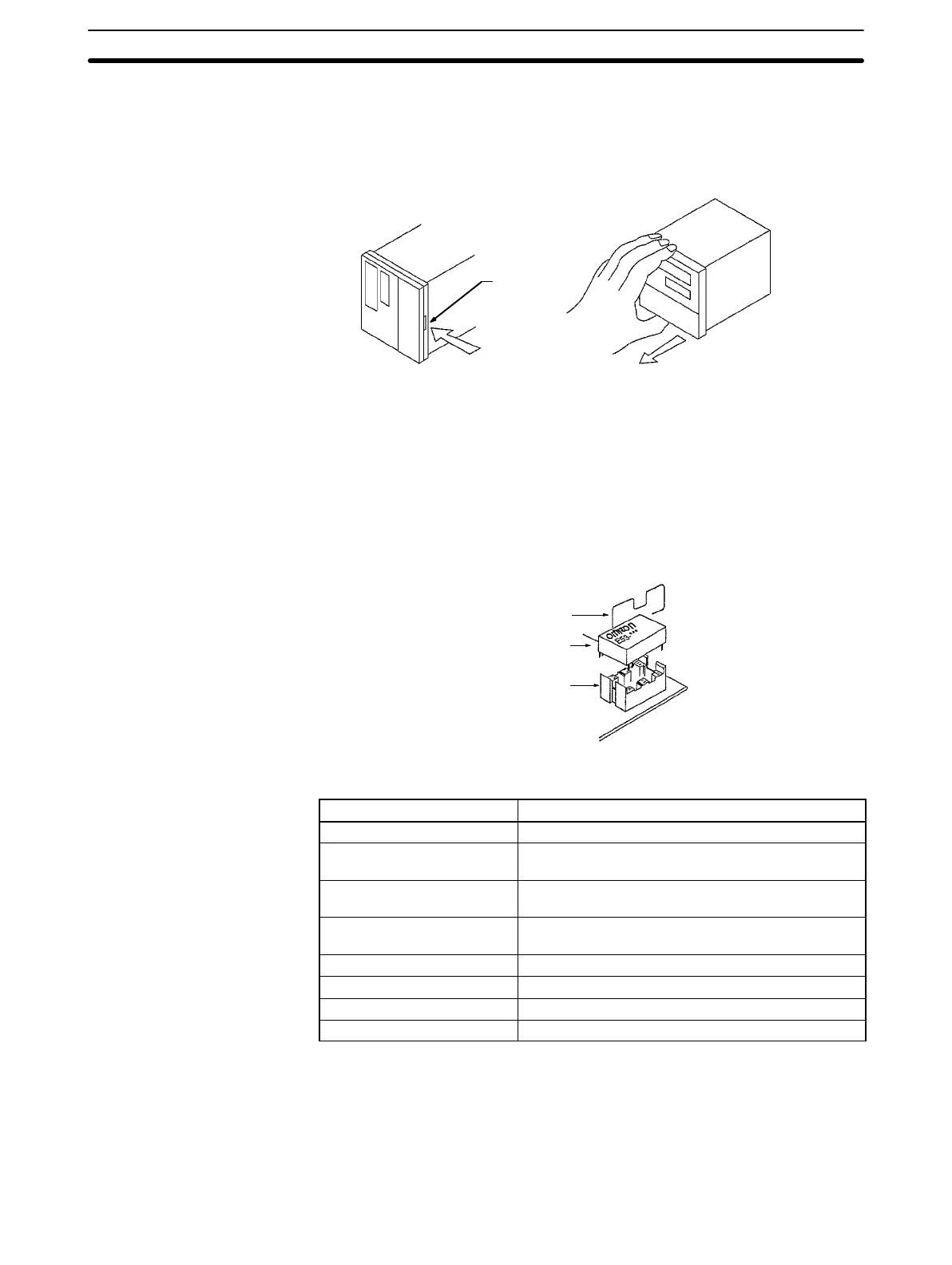
Before turning on the E5J, set its sensor type and control mode with the inter-
nal selectors. Refer to the following illustrations for disassembling the E5J to
access the internal switch settings.
Hook
Press the hook and
pull the front panel.
After setting the internal switches, insert the internal mechanism into the case
until the front panel snaps with the hook.
2-2 Output Units
Select the Output Unit according to the application and mount the Output Unit
into the socket on the E5J PCB of the as shown in the following illustration. The
E5CJ does not require an Output Unit. Refer to
1-3 Specifications
for the output
ratings of the E5J.
Bracket
Output Unit
Socket
Output Units The following Output Units are available.
Model Rating
E53-R Relay Output Unit SPDT, 5 A at 250 VAC (resistive load)
E53-Q Voltage Output Unit NPN model, 40 mA at 12 VDC (with short-circuit
protecting circuit)
E53-Q3 Voltage Output Unit NPN model, 20 mA at 24 VDC (with short-circuit
protecting circuit)
E53-Q4 Voltage Output Unit PNP model, 20 mA at 24 VDC (with short-circuit
protecting circuit)
E53-C3 Linear Output Unit 4 to 20 mA DC with a load of 600 Ω max.
E53-C3D Linear Output Unit 0 to 20 mA DC with a load of 600 Ω max.
E53-V34 Linear Output Unit 0 to 10 VDC with a load of 1 kΩ min.
E53-V35 Linear Output Unit 0 to 5 VDC with a load of 1 kΩ min.
After mounting the Output Unit, be sure to secure it with the mounting bracket
provided with the Output Unit.
If the E53-C3, E53-C3D, E53-V34, and E53-V35 Linear Output Unit is used for
control output, no heater burnout alarm is available.
Each Voltage Output Unit is used for driving an SSR as shown in the following
illustrations.
Output Units
Section 2-2