Overview
SECTION 1 Communications Methods
1-6
This section explains how to set the E5CN/AN/EN-H’s communications speci-
fications. For details on the host, refer to the User’s Manual provided with the
host.
RS-232C
A 1:1 connection is used. The maximum cable length is 15 m. To extend the
transmission path, use the OMRON Z3R RS-232C Optical Interface.
Use AWG24 (cross-sectional area: 0.205 mm
2
) to AWG14 (cross-sectional
area: 2.081 mm
2
) shielded twisted-pair cable.
RS-422 (E5AN/EN-H Only)
• Connections are 1:1 or 1:N. With 1:N, a maximum of 32 nodes including the
host can be connected.
• The maximum total cable length is 500 m.
• Use shielded twisted-pair cable (AWG28 min.).
• Connect a terminator at each end of the transmission path. In the following
example, connect a terminator to the host and to Unit #30 and not to any of
the other Units (#0 to #29).
• Use terminators with a resistance of 240
Ω (1/2 W). (The combined resistance
at both ends must be 100 Ω min.)
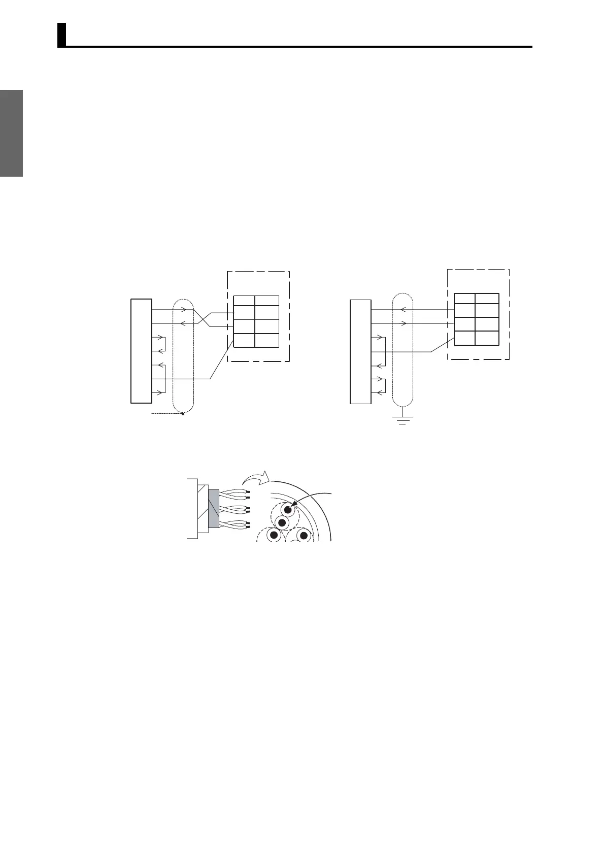
Cable Diagram
RD (RXD)
SD (TXD)
ER (DTR)
SG
DR (DSR)
RS (RTS)
CS(CTS)
3
4
5
6
7
2
8
11
No.
RS-232C
12
13
SD
RD
SG
Host (IBM PC/AT compatible)
RS-232C: 9-pin
1
FG
SD (TXD)
RD (RXD)
RS (RTS)
CS (CTS)
DR (DSR)
SG
ER (DTR)
3
4
5
6
7
20
2
11
No.
E5@N-H
RS-232C
12
13
SD
RD
SG
Host
RS-232C: 25-pin
E5@N-H
Cross-sectional area of
conductor
AWG24: 0.205 mm
2
AWG14: 2.081 mm
2
 Loading...


