2 - 53
2 Preparations
E5@C Digital Temperature Controllers User’s Manual (H174)
2-2 Using the Terminals
2
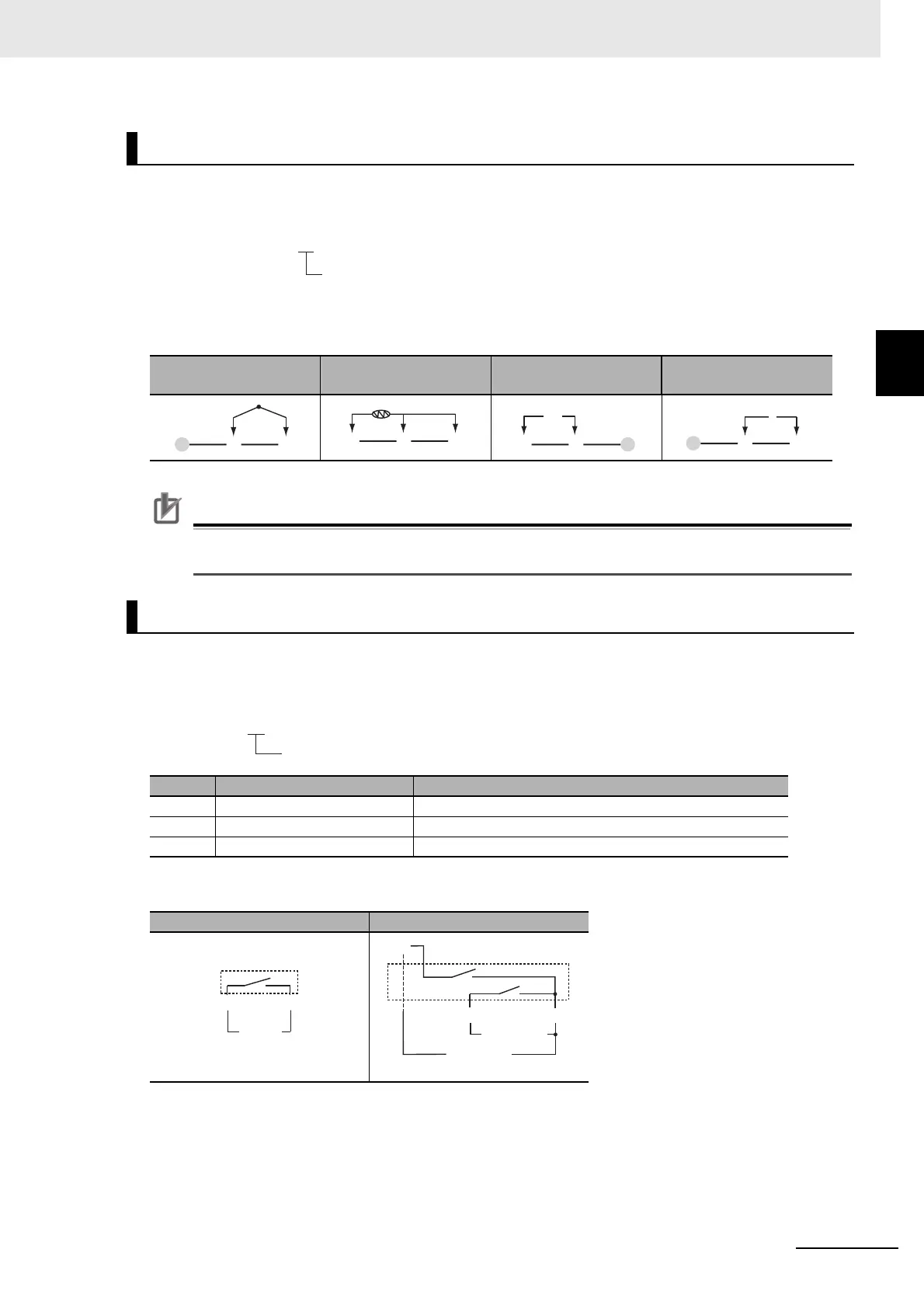
2-2-8 E5GC Terminal Block Wiring Example
Model Numbers
All E5GC models have universal sensor inputs, so the code in the model number is always “M.”
Terminal Details
Do not connect anything to the terminals that are shaded gray.
Precautions for Correct Use
When complying with EMC standards, the line connecting the sensor must be 30 m or less.
If the cable is longer than 30 m, the EMC standards will not be satisfied.
Model Numbers
The number of auxiliary outputs on the E5GC is given in the following location in the model number.
Terminal Details
Sensor Input
TC (thermocouple)
Pt (resistance
thermometer)
I (current) V (voltage)
Auxiliary Outputs
Code Auxiliary outputs Specification
0 None None
1 Model with 1 auxiliary output SPST-NO, 250 VAC, 2 A
2 Model with 2 auxiliary outputs SPST-NO, 250 VAC, 2 A
Model with 1 auxiliary output Model with 2 auxiliary outputs
E5GC-@@ @ @ @ M-@@@
Sensor input
ABB
KJL
mA
−
+
KJL
V
−
+
KJL
E5GC-@@ @ @ @ M-@@@
No. of auxiliary outputs
Auxiliary
output 1
EF
Auxiliary
output 1
Auxiliary
output 2
I
EF
 Loading...