6 - 49
6 Parameters
E5@C Digital Temperature Controllers User’s Manual (H174)
6-7 Initial Setting Level
6
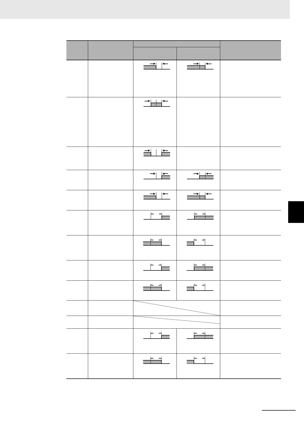
3 Lower-limit Set the downward deviation
in the set point by setting
the alarm value (X). The
alarm is ON when the PV is
lower than the SP by the
deviation or more.
4 Upper- and
lower-limit range
*1
*3 Set the upward deviation in
the set point for the alarm
upper limit (H) and the
lower deviation in the set
point for the alarm lower
limit (L). The alarm is ON
when the PV is inside this
deviation range.
5 Upper- and
lower-limit with
standby sequence
*1
*5
*4 A standby sequence is
added to the upper- and
lower-limit alarm (1).
*6
6 Upper-limit with
standby sequence
A standby sequence is
added to the upper-limit
alarm (2).
*6
7 Lower-limit with
standby sequence
A standby sequence is
added to the lower-limit
alarm (3).
*6
8 Absolute-value
upper-limit
The alarm will turn ON if the
process value is larger than
the alarm value (X)
regardless of the set point.
9 Absolute-value
lower-limit
The alarm will turn ON if the
process value is smaller
than the alarm value (X)
regardless of the set point.
10 Absolute-value
upper-limit with
standby sequence
A standby sequence is
added to the absolute-value
upper-limit alarm (8).
*6
11 Absolute-value
lower-limit with
standby sequence
A standby sequence is
added to the absolute-value
lower-limit alarm (9).
*6
12 LBA (alarm 1 type
only)
*7
13 PV change rate
alarm
*8
14 SP absolute-value
upper-limit alarm
This alarm type turns ON
the alarm when the set
point (SP) is higher than the
alarm value (X).
15 SP absolute-value
lower-limit alarm
This alarm type turns ON
the alarm when the set
point (SP) is smaller than
the alarm value (X).
Set
value
Alarm type
Alarm output operation
Description of function
When alarm value
X is positive
When alarm value
X is negative
ON
OFF
0
X
PV
ON
OFF
0
X
PV
ON
OFF
0
X
PV
ON
OFF
0
X
SP
ON
OFF
0
X
SP