1 - 11
1 Introduction
E5@C Digital Temperature Controllers User’s Manual (H174)
1-2 I/O Configuration and Model
Number Legend
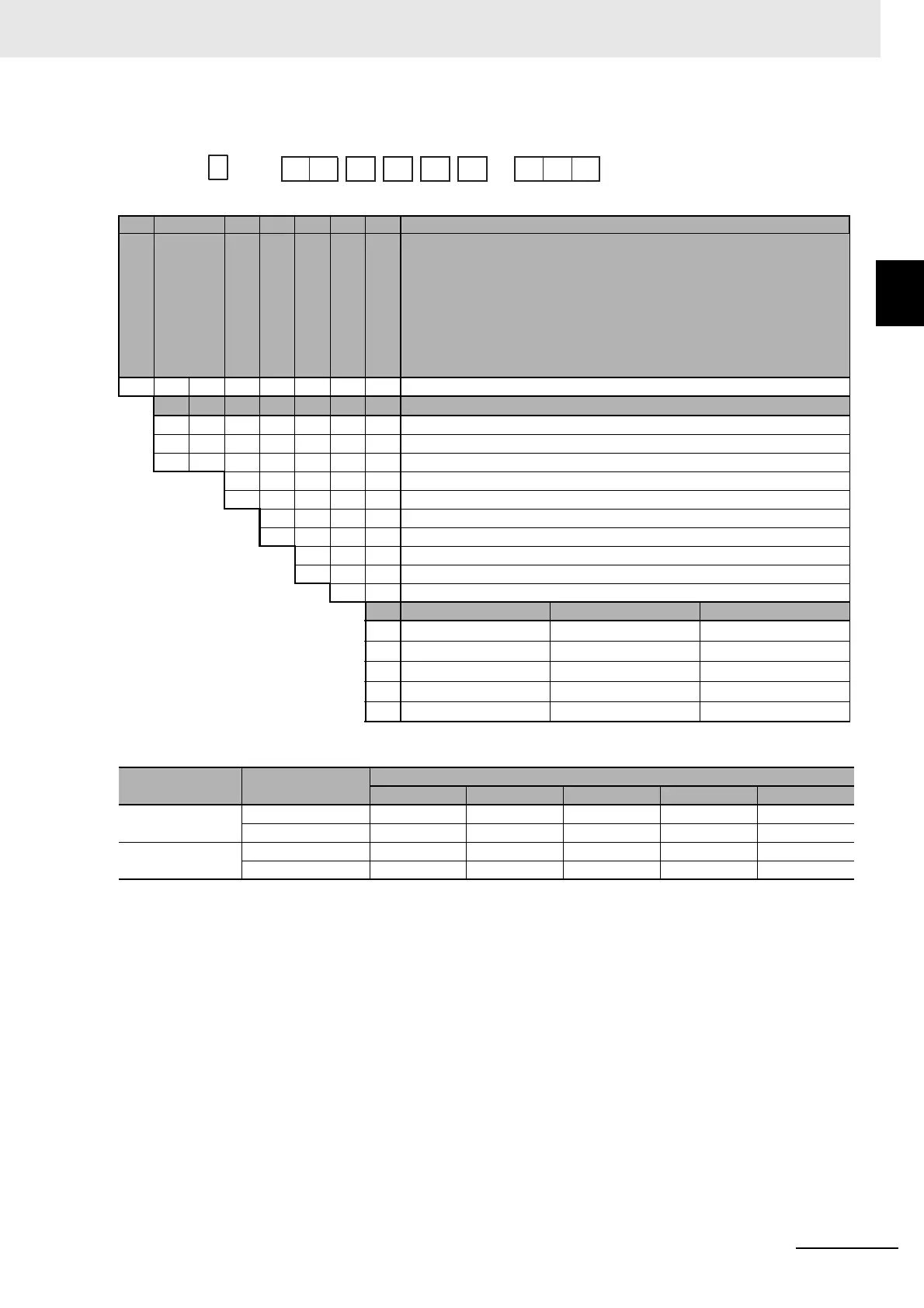
1
1-2-2 Model Number Legends
E5DC
*1 The options that can be selected depend on the type of control output and number of auxiliary outputs.
*2 The control output can be used as a simple transfer output for Digital Controllers manufactured in July 2014 or later
(version 2.2 or higher).
(1) (2) (3) (4) (5) (6) (7) Meaning
D 22.5 mm wide and mounts to DIN Track
Control output 1
*1 R X Relay output
*1 Q X Voltage output (for driving SSR)
*1*2 C X Linear current output
*1 0 None
*1 2 2
A 100 to 240 VAC
D 24 VAC/DC
S Terminal screw block (Main Unit and Terminal Unit together)
U Main Unit only (no Terminal Unit)
M Universal input
Event inputs Communications HB alarm and HS alarm
000 --- --- ---
002 --- RS-485 1
015 --- RS-485 ---
016 1 --- ---
017 1 --- 1
Control output
No. of auxiliary
outputs
Options
000 002 015 016 017
RX or QX 0 --- --- Selectable --- ---
2 Selectable Selectable --- --- Selectable
CX 0 --- --- Selectable --- ---
2 Selectable --- Selectable Selectable ---
E5DC
−
(1) (2) (3) (4) (5) (6) (7)
−