1 - 13
1 Introduction
E5@C Digital Temperature Controllers User’s Manual (H174)
1-2 I/O Configuration and Model
Number Legend
1
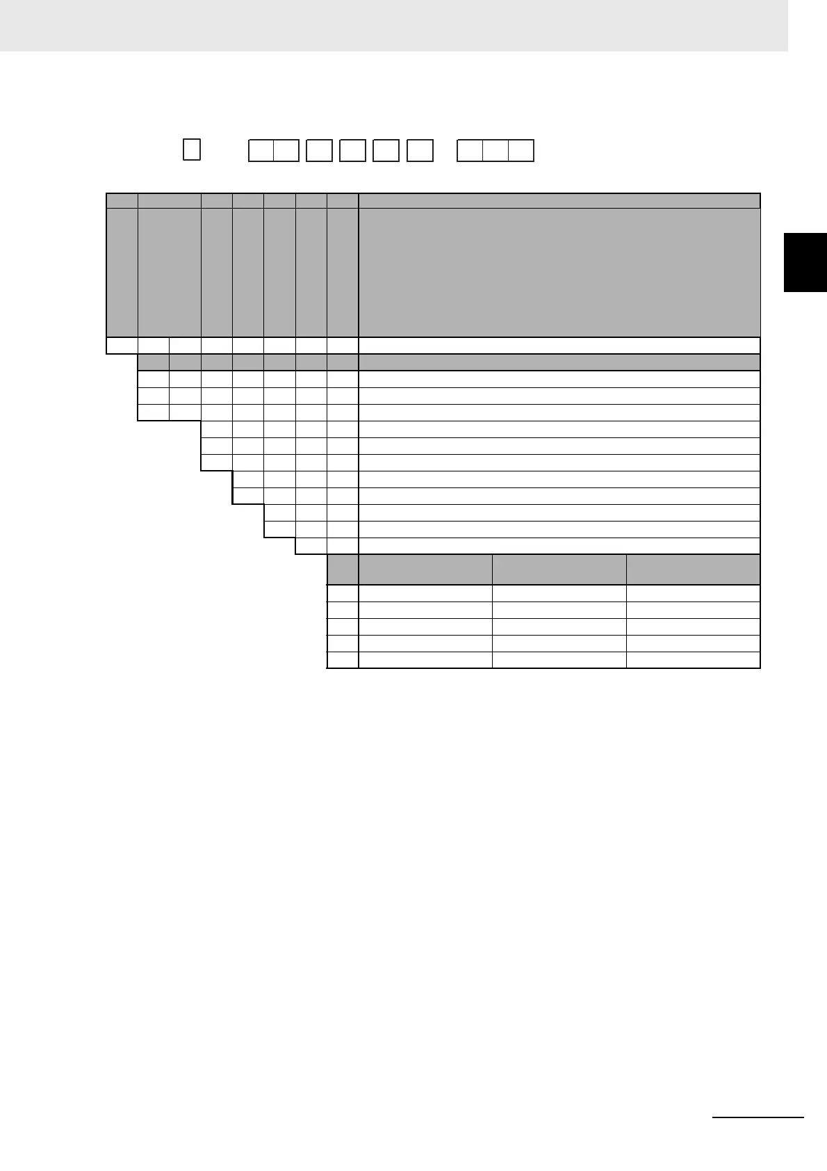
1-2-2 Model Number Legends
E5GC
*1 The control output can be used as a simple transfer output.
*2 If no auxiliary outputs (none) is selected, 000 (none) must be selected for the options.
*3 These options can be selected only if two auxiliary outputs are selected.
*4 The option for HB and HS alarms (023) cannot be selected if a linear current output is selected for the control output.
*5 This option can be selected only if one auxiliary output is selected.
(1) (2) (3) (4) (5) (6) (7) Meaning
G 48 × 24 mm
Control output 1
R X Relay output
Q X Voltage output (for driving SSR)
*1 C X Linear current output
*2 0 None
11
22
A 100 to 240 VAC
D 24 VAC/DC
6 Screw terminals (with cover)
C Screwless clamp terminals
M Universal input
Event inputs Communications
Single-phase HB alarm
and HS alarm
000 --- --- ---
015 --- RS-485 ---
*3 016 1 --- ---
*3*4 023 --- --- 1
*5 024 2 --- ---
E5GC
−
(1) (2) (3) (4) (5) (6) (7)
−