7 User Calibration
7 - 6
E5@C Digital Temperature Controllers User’s Manual (H174)
6. When the M Key is pressed, the status changes as shown to the left.
Set the STV to −6 mV.
Allow the count value on the No. 2 display to fully stabilize, then press the D Key
to temporarily register the calibration settings.
If this count value is outside of the specified range, the No. 2 display will flash and
the count value will not be temporarily registered.
7. When the M Key is pressed, the status changes as shown to the left.
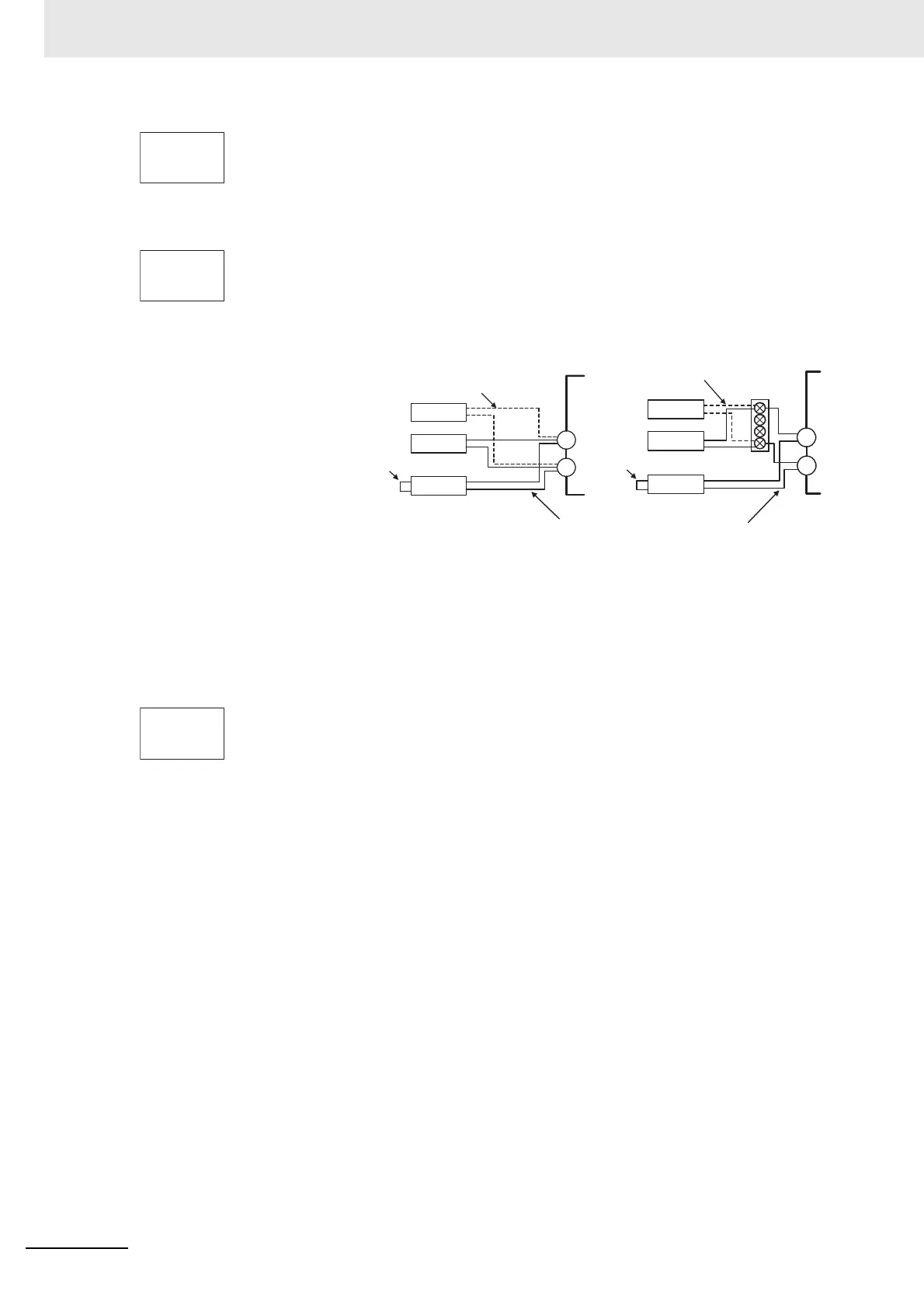
8. Change the wiring as follows:
Disconnect the STV to enable the thermocouple of the cold junction compensator.
When doing this, be sure to disconnect the wiring on the STV side.
9. Allow the count value on the No. 2 display to fully stabilize, then press the D Key
to temporarily register the calibration settings.
10. When the M Key is pressed, the status changes as shown to the left.
The data to be temporarily registered is not displayed if it is not complete.
Press the U Key. The No. 2 display changes to yes. Release the key and wait
two seconds or press the M Key. This stores the temporarily registered
calibration data to non-volatile memory. To cancel the saving of temporarily
registered calibration data to non-volatile memory, press the M Key (while no is
displayed in the No. 2 display) without pressing the U Key.
11. The calibration mode is ended by turning the power OFF.
For Digital Controllers that have a transfer output, you can continue by calibrating
the transfer output. For detailed setting methods, refer to 7-6 Calibrating the
Transfer Output.
t -6
2988
bia5
35b8
STV
DMM
Zero controller
−
+
OUTPUT INPUT
Connect.
Open in non-connected state
Connect.
Open in non-connected state
STV
DMM
Zero controller
−
+
OUTPUT INPUT
Relay
terminal block
E5@C-B or E5GC
E5CC, E5CC-U, E5EC, E5AC, or E5DC
Compensating conductor of currently selected
thermocouple
Use K thermocouple compensating conductor for E, R, S, B,
W, and PLII thermocouples and for an infrared temperature
sensor.
str
no