7 User Calibration
7 - 14
E5@C Digital Temperature Controllers User’s Manual (H174)
Use the following procedure to calibrate the transfer output for 1 to 5 V.
5. To cancel saving the temporarily registered calibration data to non-volatile
memory, press the M Key without pressing the U Key, i.e., while no is displayed
in the No. 2 display.
Press the U Key. The No. 2 display changes to yes. Release the key and wait 2
seconds or press the M Key. This saves the temporarily registered calibration data
in non-volatile memory.
6. The Calibration Mode is ended by turning OFF the power supply.
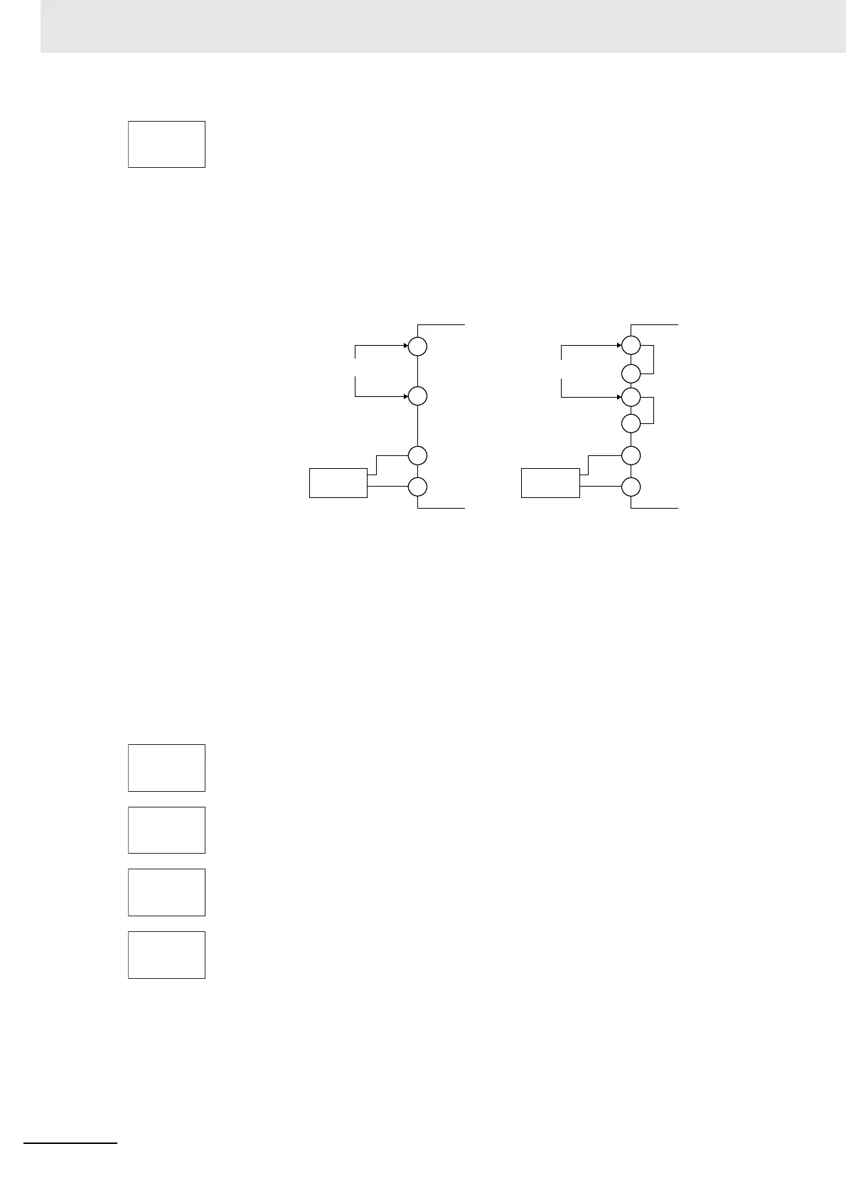
1. Connect a DMM to the transfer output terminals.
2. Press the M Key to display the parameter for the transfer output.
3. The calibration display for 5 V will be displayed. Press the U or D Key until the
DMM monitor value changes to 5 V.
Press the M Key. The calibration settings will be temporarily registered.
4. The calibration display for 1 V will be displayed. Press the U or D Key until the
DMM monitor value changes to 1 V.
Press the M Key. The calibration settings will be temporarily registered.
5. To cancel saving the temporarily registered calibration data to non-volatile
memory, press the M Key without pressing the U Key, i.e., while no is displayed
in the No. 2 display.
Press the U Key. The No. 2 display changes to yes. Release the key and wait 2
seconds or press the M Key. This saves the temporarily registered calibration data
in non-volatile memory.
6. The Calibration Mode is ended by turning OFF the power supply.
str.t
no
Input power supply
Input power supply
DMM
E5CC/E5EC/E5AC
+
−
DMM
E5@C-B
+
−
*
*
* Common terminals are indicated with asterisks (*).
C
D
C
C'
D
D'
The terminal numbers are as follows:
• Transfer Output Terminals (Positive
and Negative)
E5CC: 16 and 18
E5EC/E5AC: 31 and 33
• Input Power Supply (C/D)
E5CC: 11 and 12
E5EC/E5AC: 1 and 2
The terminal numbers are as follows:
• Transfer Output Terminals (Positive
and Negative)
E5CC-B: 22 and 24
E5EC-B: 42 and 44
• Input Power Supply (C or C', and D
or D')
E5CC-B: 13 or 14, and 15 or 16
E5EC-B: 1 or 2, and 3 or 4
str
no
v 5.t
5680
V 1.t
0001
str.t
no