2 - 37
2 Preparations
E5@C Digital Temperature Controllers User’s Manual (H174)
2-2 Using the Terminals
2
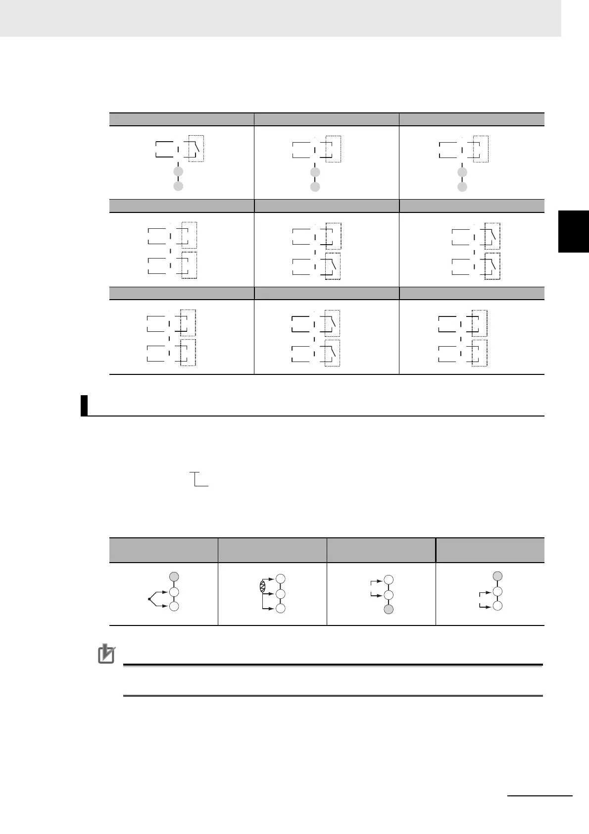
2-2-4 E5EC/E5AC Terminal Block Wiring Example
Terminal Details
Do not connect anything to the terminals that are shaded gray.
Model Numbers
All models have universal sensor inputs, so the code in the model number is always “M.”
Terminal Details
Do not connect anything to the terminals that are shaded gray.
Precautions for Correct Use
When complying with EMC standards, the line connecting the sensor must be 30 m or less. If the
cable length exceeds 30 m, compliance with EMC standards will not be possible.
RX QX CX
QQ QR RR
CC PR CQ
Sensor Input
TC (thermocouple)
Pt (resistance
thermometer)
I (current) V (voltage)
C
E
D
F
Relay output
Control output 1
+
−
C
E
D
F
Voltage output
(for driving SSR)
Control output 1
+
C
E
D
F
Linear current
output
Control output 1
−
C
E
D
F
+
Voltage output
(for driving SSR)
Voltage output
(for driving SSR)
+
Control output 1
Control output 2
−
−
Relay output
C
E
D
F
+
Voltage output
(for driving SSR)
Control output 1
Control output 2
−
C
E
D
F
Relay output
Relay output
Control output 1
Control output 2
C
E
D
F
+
+
Control output 1
Control output 2
−
−
Linear current
output
Linear current
output
C
E
D
F
Relay output
Relay output
Open
Close
C
E
D
F
+
Voltage output
(for driving SSR)
+
Control output 1
Control output 2
−
−
Linear current
output
E5EC-@@ @ @ S M-@@@
Sensor input
−
+
22
23
24
A
B
B
22
23
24