E5EX–H
E5EX–H
8
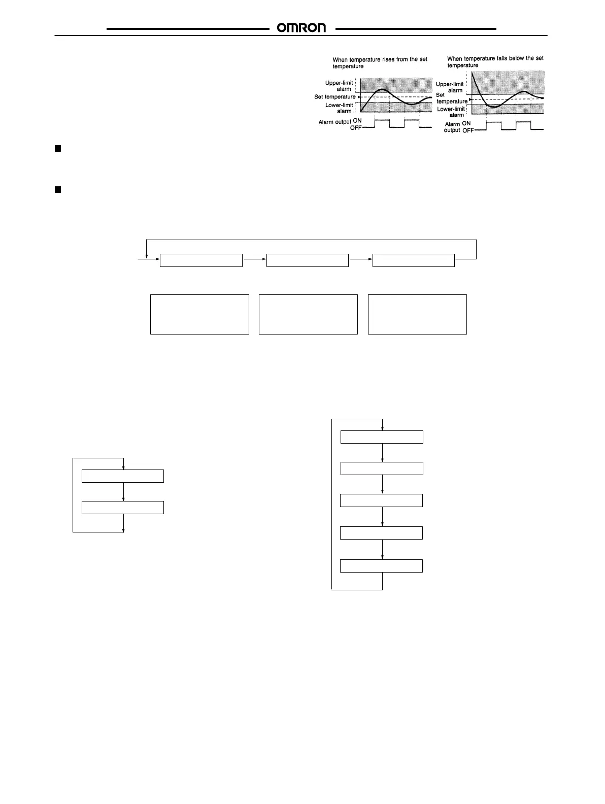
Standby Sequence
Alarm
functions with standby sequence suppress nuisance alarms
when
the controller is first powered up. As shown
in the temperature
charts
at right, the alarm output is suppressed until the temperature
exceeds
the alarm band or alarm limit one time.
Protection Switch (SW101, PROTECT)
When the protection switch is set to the ON position, the level key, up and down keys, and auto-tuning key will not operated. In effect, the
Temperature
Controller is write-protected and the set values (such as the alarm value) can be read out only
.
Inputting Parameters
The
T
emperature Controller has three indication levels, 0, 1, and 2, in which only specific parameters can be set. Level 0 is the default and is
automatically
entered during power up. T
o change the mode to manipulate a dif
ferent group of parameters, hold down the
level key for 2 sec
-
onds
or more. The indication level mode changes as shown below
.
–––––––
–––––––
–––––––
Level 0
Power up
Level 1 Level 2
Press the level key. Press the level key. Press the level key.
Process temperature,
alarm value, input shift,
PID constants
Setting limits, control peri
-
od, hysteresis, heater cur
-
rent, heater burnout set
-
ting
Control output variable,
temperature sensor type,
alarm mode
Level 0
In
this
mode, parameters such as the alarm values, PID constants,
and input shift values
can
be set or changed. When these parame
-
ters are being set or changed, the new values are displayed on the
SV display
. The parameter to be manipulated is selected by press
-
ing the display key the required number of times. Note that the PID
constants
are displayed
only when pin 1 on the operating mode se
-
lector
DIP switch (SW201) is set
to the OFF position and pin 6 to the
ON position. (The flow chart shown below assumes the settings are
as
preset at the factory
.)
Process temperature
Power up (temperature
setting)
Press a.
Press a.
Alarm value
al
After
al
has been displayed, press the display key again. Then the
PID constants can be manually set or changed, provided pin 6 on
the internal operating mode selector (SW201) has been set to the
ON
position. The message displayed on the PV
display changes as
shown
below each time the display key is pressed.
Process temperature
Power up (temperature
setting)
Press a.
Press a.
Press a.
Press a.
Press a.
Alarm value
Proportional band
Integral time
Derivative time
i
d
al
p