12 Modular Temperature Controller EJ1
Restrictions on Unit Placement
Always connect the HFU on the left side of the Basic Unit. Do not connect the End Unit directly to the HFU.
Always connect a Basic Unit to the End Unit.
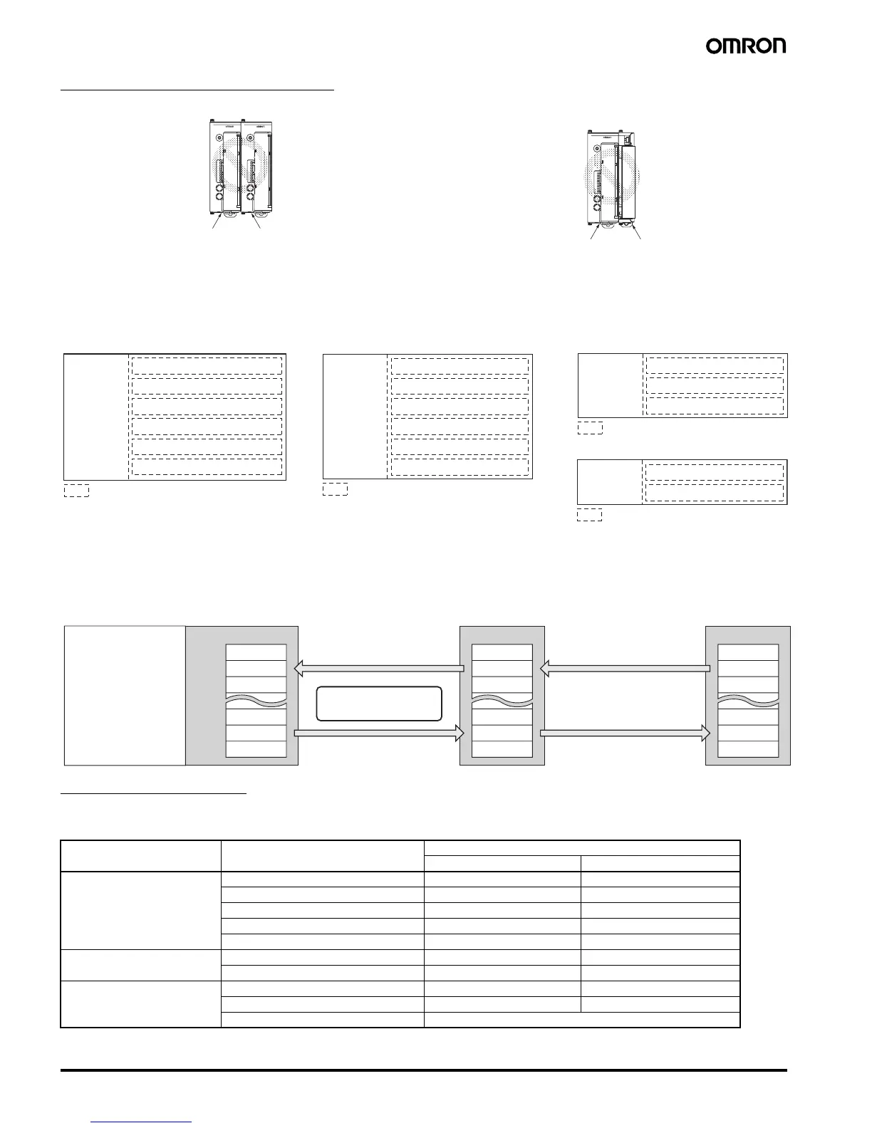
■ Insulation Blocks
Each EJ1 Unit is electrically insulated for each function block as shown in the following figures.
Functional insulation is applied between the power supply, input, output, and communications terminal sections.
If reinforced double insulation is required, use power supplies that comply with IEC60664 for reinforced double insulation for the EJ1's external
power supply and for power supplies connected to the EJ1.
■ Programless Communications
Communications with PLCs from OMRON (SYSMAC CS/CJ/CP1H Series) and Mitsubishi Electric (MELSEC-Q/QnA/QnAS/An/Ans/FX
3UC
Series)
can be performed without creating ladder programming.
Using programless communications enables monitoring and changing settings for the EJ1 by simply reading and writing to PLC memory.
The EJ1 automatically performs communications with the PLC, which reduces work hours spent programming for communications from the PLC
to the EJ1.
Connectable Devices
Connecting an EJ1 Controller 1:1 to a PLC
SYSMAC CS/CJ Series
Note: Use only products manufactured on or after December 20, 1999.
For details, refer to the CS/CJ Series, Serial Communications Boards Operation Manual (Cat. No. W336).
COM1
COM2
COM3
PWR
RUN
ERR
ALM
SW1
ON
SW2
21345678
EJ1-HFU
0
1
2
3
4
5
6
7
8
9
A
B
C
D
E
F
COM1
COM2
COM3
PWR
RUN
ERR
ALM
SW1
ON
SW2
21345678
EJ1-TC4
0
1
2
3
4
5
6
7
8
9
A
B
C
D
E
F
EJ1N-HFUEJ1N-TC4 or
EJ1N-TC2
COM1
COM2
COM3
PWR
RUN
ERR
ALM
SW1
ON
SW2
21345678
EJ1-HFU
0
1
2
3
4
5
6
7
8
9
A
B
C
D
E
F
EJ1N-HFU EJ1C-EDU
Name Model No. Communications ports
Port 1 Port 2
Serial Communications Units CJ1W-SCU21-V1 RS-232C RS-232C
CJ1W-SCU31-V1 RS-422A/485 RS-422A/485
CJ1W-SCU41-V1 RS-422A/485 RS-232C
CS1W-SCU21-V1 (See note.) RS-232C RS-232C
CS1W-SCU31-V1 RS-422A/485 RS-422A/485
Serial Communications Boards CS1W-SCB21-V1 (See note.) RS-232C RS-232C
CS1W-SCB41-V1 (See note.) RS-232C RS-422A/485
CPU Units CJ1 Series --- RS-232C
CS1 Series --- RS-232C
CP1H Series RS-232C or RS-422A/485 can be used by adding an Option Board.
Power
supply
Transistor outputs 1 to 4
Communications (Port B, port C)
Event inputs 1 to 4
Functional isolation
Power
supply
Transistor outputs 1 and 2
Communications (Port A, port B)
Functional isolation
EJ1N-HFU
Input 1
Power
supply
Input 2
Event inputs 1 and 2, CT1 and 2
(See note.)
Communications (Port A, port B, G3ZA)
Transistor outputs 3 and 4
Voltage outputs 1 and 2/Current outputs 1 and 2
Functional isolation
Input 1
Power
supply
Input 2
Input 4
Voltage outputs 1 to 4
Communications (Port A, Port B, G3ZA)
Input 3
Functional isolation
EJ1N-TC2 EJ1N-TC4
EJ1C-EDU
Note: Not provided on models with current outputs.
PV
PLC
The read monitor value is
written to the PLC memory.
The read setting is written to the
setting for the EJ1N-TC4/TC2.
Manipulated variable
Status
SP
Monitor
Setting
Alarm value 1
Alarm value 2
EJ1N-HFU EJ1N-TC4/TC2
The EJ1N-HFU automatically
performs communications
with the PLC.
The EJ1N-HFU reads the value
written to the PLC memory.
The EJ1N-HFU reads the monitor
value for the EJ1N-TC4/TC2.
Monitoring can be
performed for the
EJ1 and the settings
can be changed by
simply reading and
writing to memory.
PV
Manipulated variable
Status
SP
Alarm value 1
Alarm value 2
PV
Manipulated variable
Status
SP
Alarm value 1
Alarm value 2

 Loading...


