Modular Temperature Controller EJ1 15
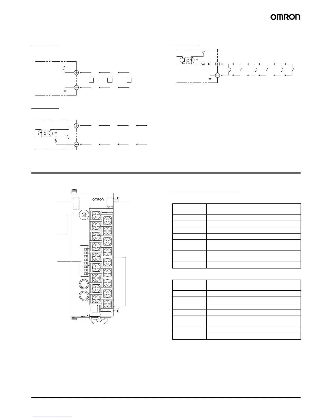
■ Internal Wiring
Circuit 1
*Models with Pulse Outputs)
Circuit 2
Circuit 3
Nomenclature and Specification Settings
■ Nomenclature
Operation Indicators
EJ1N-TC2/TC4
EJ1N-HFU
Note: A certain period of time is required for the indicators to light
after the power is turned ON.
L
+V
GND
B1/B2
EJ1N
-TC4
B3
L
B1/B2
EJ1N
-TC2
B3
A1/A2
EJ1N
-TC4
A3
L
A1/A2
EJ1N
-TC2
A3
B1/B2
EJ1N
-HFU
B3
B4/B5
EJ1N
-HFU
B6
3/4
EJ1C
-EDU
5
+V
GND
A6
A4/A5
EJ1N
-TC2
A3
A1/A2
EJ1N
-HFU
A6
A4/A5
EJ1N
-HFU
COM1
COM2
COM3
EJ1-
PWR
RUN
ERR
ALM
SW1
ON
SW2
21345678
0
1
2
3
4
5
6
7
8
9
A
B
C
D
E
F
Operation
Indicators
COM1
COM2
COM3
Operation
Indicators
PWR
RUN
ERR
ALM
SW1
SW2
Operation
Indicators
Meaning
PWR (green) Lit while the power is ON.
RUN (green) Lit during operation.
ERR (red) Flashes or lights when an error occurs.
ALM (red) Lights when an alarm is activated.
COM 1 (orange) Flashes during communications using port A on
the End Unit.
COM 2 (orange) Flashes during communications using port B on
the End Unit.
COM 3 (orange) Flashes during communications with the G3ZA.
Operation
Indicators
Meaning
PWR (green) Lit while the power is ON. (See note.)
RUN (green) ---
ERR (red) Flashes or lights when an error occurs.
ALM (red) Lights when an alarm is activated.
COM 1 (orange) Flashes during communications using port A on
the End Unit.
COM 2 (orange) Flashes when the EJ1 system is in operation.
COM 3 (orange) Flashes during communications using port C.

 Loading...


