Solid State Relays G3NA 7
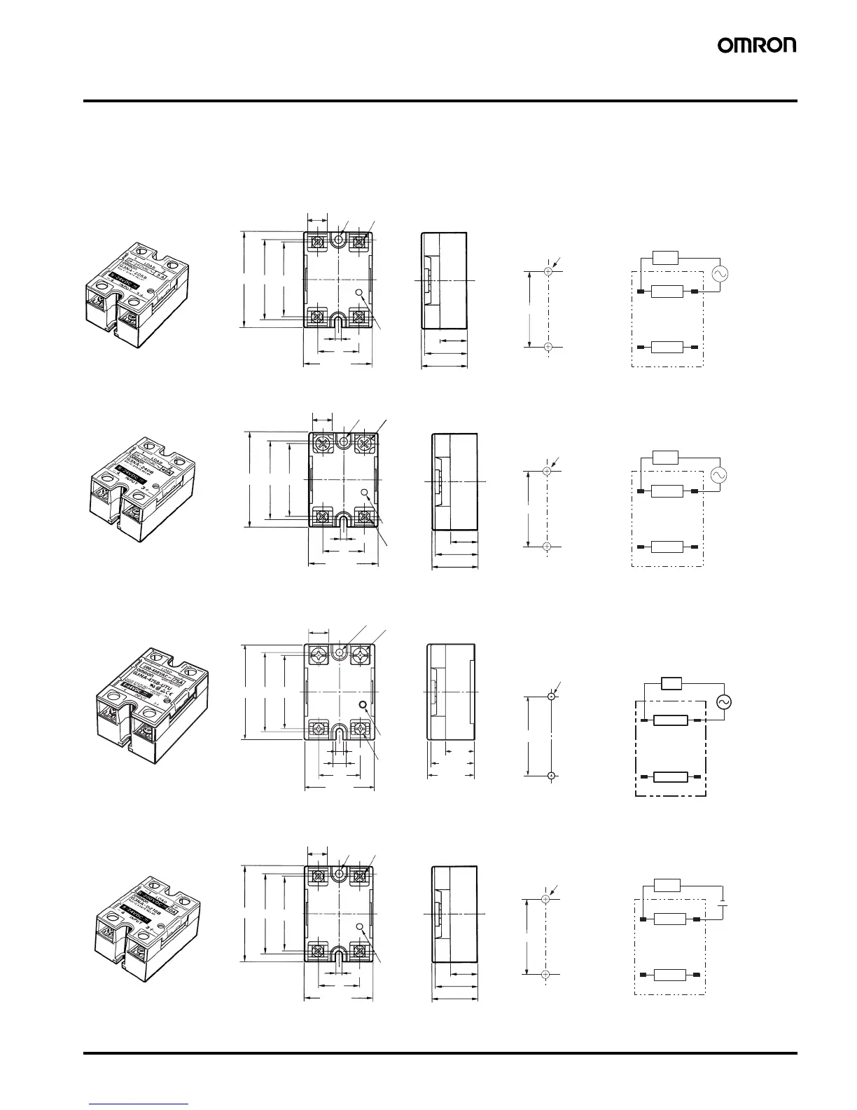
Dimensions
■ Relays
Note: All units are in millimeters unless otherwise indicated.
G3NA-205B-UTU, G3NA-210B-UTU, G3NA-220B-UTU, G3NA-410B-UTU, G3NA-425B-UTU
13.8
12
34
(−) (+)
4.5
25
47.5
44
47.6±0.2
25 max.
27 max.
Mounting Holes
Output
Input
Load
4.5 dia.
43 max.
58 max.
Operating
indicator
Four, M4 x 8
screws
Two, 4.3-dia.
or M4 holes
Terminal Arrangement/
Internal Connections
(Top View)
Load
power
supply
11.9
47.6
±0.2
12
34
(−) (+)
G3NA-240B-UTU, G3NA-250B-UTU, G3NA-450B-UTU
13.8
47.5
44
4.5
25
11.9
Mounting Holes
Output
Input
Load
25 max.
27 max.
58 min.
4.5 dia.
Two, M5 x 12 screws
43 max.
Two,
M 4 x 8
Operating
indicator
Two, 4.3-dia.
or M4 holes
Load
power
supply
Terminal Arrangement/
Internal Connections
(Top View)
G3NA-275B-UTU, G3NA-475B-UTU, G3NA-290B-UTU, G3NA-490B-UTU
16.8
47.5 44
25
8.2
12
4.5
47.6
±
0.2
12
(−)
4
(+)
3
Mounting Holes
Output
Input
Load
4.5 dia.
Two, M5 x 12
screws
Operating
indicator
Two, 4.3-dia.
or M4 holes
Terminal Arrangement/
Internal Connections
(Top View)
Load
power
supply
Two, M4 x
8 screws
43 max.
58 max.
26 max.
28 max.
G3NA-D210B-UTU
13.8
47.6±0.2
12
34
(−) (+)
− +
4.5
25
47.5 44
Note: The load can be connected to either the positive or negative side.
11.9
25 max.
27 max.
Mounting Holes
Output
Input
Load
4.5 dia.
43 max.
58 max.
Four, M4 x 8
screws
Operating
indicator
Two, 4.3-dia.
or M4 holes
Terminal Arrangement/
Internal Connections
(Top View)
Load
power
supply
Note: When connecting the load, either the
positive or negative side of the load
terminals can be connected.