Single-phase Solid State Relays for Heaters G3PE 449
Dimensions
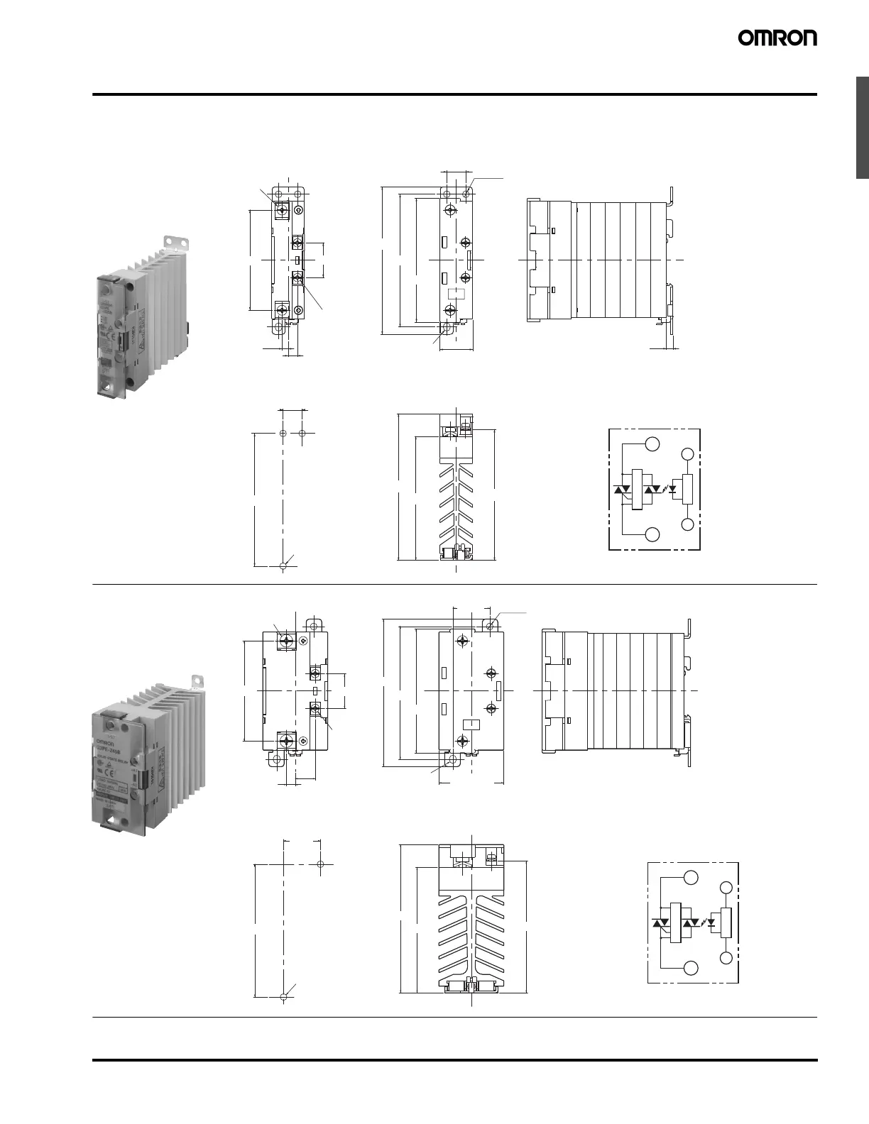
Note: All units are in millimeters unless otherwise indicated.
Solid State Relays
Two, M4
68
4.2
6.3
Two,
M3.5
Note: Without terminal cover.
24
13
±0.2
Two,
4.6 dia.
100 max.
90
±0.2
84
22.5 max.
4.6 × 5.6
elliptical hole
Note: With terminal cover.
4.5
(90)
(85)
(100)
90
±0.3
Three, 4.5 dia.
or M4
Mounting Holes
13
±0.3
1
2
A1
A2
(+)
( − )
G3PE-5@@B
Terminal Arrangement/Internal Circuit Diagram
Output side
t i u c r i c r e g g i r T
Input side
t i
u
c r
i c
t
u
p n
I
1
2
A1
A2
(+)
(−)
G3PE-2@@B
Input side
Output side
tiucric reggirT
t
iu
cr
i
c t
u
pn
I
68
13.5
6
Two, M5
Two,
M3.5
Note: Without terminal cover.
4.6 dia.
4.6 × 5.6
elliptical hole
Note: With terminal cover.
90
±0.3
Three, 4.5 dia.
or M4
Mounting Holes
Terminal Arrangement/Internal Circuit Diagram
1
2
A1
A2
(+)
(−)
G3PE-5@@B
Output side
tiucric reggirT
Input side
ti
u
cr
ic
t
u
pn
I
1
2
A1
A2
(+)
(−)
G3PE-2@@B
Input side
Output side
tiucric reggirT
t
iu
cr
i
c t
u
pn
I
25
±0.3
(100)
(85)
(90)
100 max.
90
±0.2
84
25
±0.2
44.5 max.
24

 Loading...


