G-115G9SA
G9SA
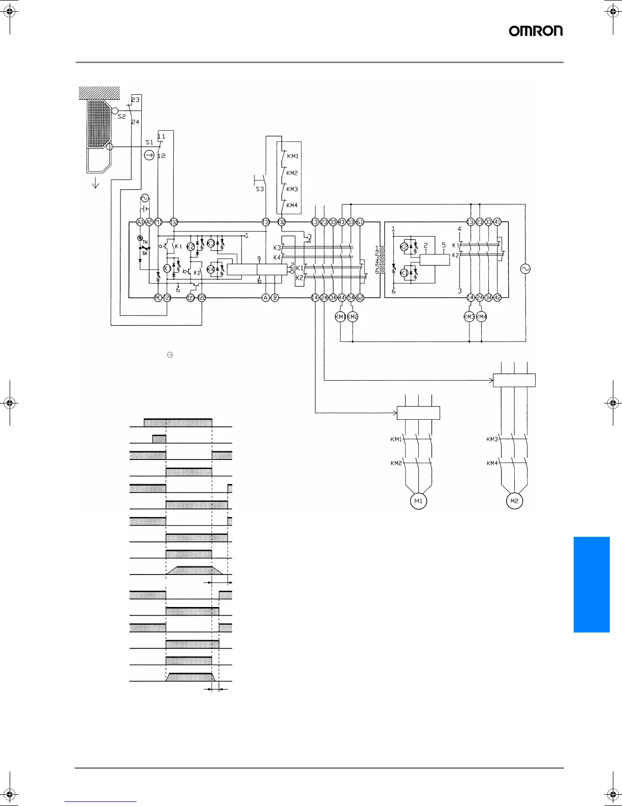
G9SA-321-T# (24 VAC/VDC) + G9SA-EX031-T# with 2-channel Limit Switch Input/Manual-reset
Feedback loop
Motor controller
Timing Chart
OFF-delay time 1
OFF-delay time 2
Open
Motor controller
Off delay
timer
Control
circuit
Off delay
timer
Operation
instruction
Operation
instruction
S1: Safety Limit Switch
with direct opening mechanism
(D4N or D4B)
S2: Limit switch
S3: Reset switch
KM1, KM2,
KM3, and KM4: Magnetic Contactor
M1, M2: 3-phase motor
Limit switches
S1 and S2
Reset switch
S3
G9SA-321-T#
K1 and K2 (NC)
G9SA-321-T#
K1 and K2 (NO)
G9SA-321-T#
K3 and K4 (NC)
G9SA-321-T#
K3 and K4 (NO)
KM1 and KM2
(NC)
KM1 and KM2
(NO)
Operation
instruction
Motor M1
rotation
G9SA-EX031
K1 and K2 (NC)
G9SA-EX-031
K1 and K2 (NO)
KM3 and KM4
(NC)
KM3 and KM4
(NO)
Operation
instruction
Motor M2
rotation
Note: This circuit achieves EN954-1 Safety Category 4.
The OFF-delay output, however, achieves EN954-1
Safety Category 3.
F502-EN2-04.book Seite 115 Dienstag, 26. Juli 2005 5:48 17

 Loading...


